Aluminum electrolytic capacitors Snap-in capacitors Series/Type: B43504 Date: December 2013 © EPCOS AG 2013. Reproduction, publication and dissemination of this publication, enclosures hereto and the information contained therein without EPCOS' prior express consent is prohibited.
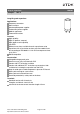
Snap-in capacitors B43504 Compact 105 °C Long-life grade capacitors Applications Frequency converters Solar inverters Uninterruptible power supplies Professional power supplies Medical appliances Telecommunications Features High reliability High CV product, compact High ripple current capability Low ESR Different case sizes available for each capacitance value Capacitors with all insulation versions pass the needle flame test according to IEC 60695-11-5 for all flame exposure times up to 120 s RoHS-com
B43504 Compact 105 °C Specifications and characteristics in brief Rated voltage VR Surge voltage VS Rated capacitance CR Capacitance tolerance 200 ... 450 V DC 1.15 VR (for VR ≤ 250 V DC) 1.10 VR (for VR ≥ 400 V DC) 47 ... 2200 µF ±20% M Dissipation factor tan δ (20 °C, 120 Hz) VR ≤ 400 V DC: tan δ ≤ 0.15 VR ≥ 420 V DC: tan δ ≤ 0.20 Leakage current Ileak (5 min, 20 °C) Self-inductance ESL Useful life1) 105 °C; VR; IAC,R 85 °C; VR; IAC, max 40 °C; VR; 1.
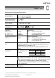
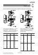
B43504 Compact 105 °C Dimensional drawings Snap-in capacitors with standard insulation (PVC or PET) Snap-in terminals, length (6.3 ±1) mm. Also available in a shorter version with a length of (4.5 1) mm. PET insulation is marked with label "PET" on the sleeve. Snap-in capacitors are also available with 3 terminals (length (4.5 1) mm). PET insulation is marked with label "PET" on the sleeve.
B43504 Compact 105 °C Snap-in capacitors with PVC insulation and PET insulation cap on terminal side Snap-in terminals, length (6.3 +1/ 1.4) mm. Also available in a shorter version with a length of (4.5 1.4) mm. PET insulation cap is positioned under the insulation sleeve. Snap-in capacitors are also available with 3 terminals (length (4.5 1.4) mm). PET insulation cap is positioned under the insulation sleeve. Dimensions (mm) d +1.4 l +2.
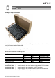
B43504 Compact 105 °C Packing of snap-in capacitors For ecological reasons the packing is pure cardboard. Components can be withdrawn (in full or in part) in the correct position for insertion. Ordering codes for terminal styles and insulation features Identification in 3rd block of ordering code Snap-in capacitors Terminal version Insulation version PVC PET PVC plus PET cap Standard terminals 6.3 mm M000 M060 M080 Short terminals 4.5 mm M007 M067 M087 3 terminals 4.
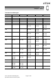
B43504 Compact 105 °C Overview of available types VR (V DC) 200 250 400 420 450 Case dimensions d × l (mm) CR (µF) 47 22 × 25 68 22 × 25 22 × 30 82 22 × 30 22 × 30 22 × 35 100 22 × 35 25 × 25 22 × 35 25 × 30 22 × 35 25 × 30 30 × 25 120 22 × 35 22 × 40 25 × 30 25 × 35 150 22 × 40 30 × 25 25 × 35 30 × 30 25 × 40 30 × 30 35 × 25 180 25 × 40 30 × 30 25 × 40 30 × 30 25 × 45 220 22 × 25 22 × 30 25 × 45 30 × 35 35 × 25 25 × 45 30 × 35 25 × 50 30 × 40 35 × 30 270 22 × 25 22
B43504 Compact 105 °C VR (V DC) 200 250 400 420 450 Case dimensions d × l (mm) CR (µF) 1000 25 × 50 30 × 35 35 × 30 30 × 45 35 × 40 1200 30 × 40 30 × 55 35 × 40 1500 30 × 50 35 × 40 35 × 50 1800 35 × 45 35 × 55 2200 35 × 50 The capacitance and voltage ratings listed above are available in different cases upon request. Other voltage and capacitance ratings are also available upon request. Please read Cautions and warnings and Important notes at the end of this document.
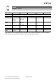
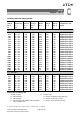
B43504 Compact 105 °C Technical data and ordering codes CR 100 Hz 20 °C µF Case dimensions d×l mm VR = 200 V DC 220 22 × 25 270 22 × 25 330 22 × 30 390 22 × 30 470 22 × 35 470 25 × 30 470 30 × 25 560 25 × 35 680 25 × 40 680 30 × 30 680 35 × 25 820 25 × 45 820 35 × 30 1000 25 × 50 1000 30 × 35 1000 35 × 30 1200 30 × 40 1500 30 × 50 1500 35 × 40 1800 35 × 45 2200 35 × 50 VR = 250 V DC 220 22 × 30 270 22 × 30 330 22 × 35 330 25 × 30 390 25 × 35 470 22 × 45 470 30 × 30 560 25 × 40 680 25 × 50 IAC,max 100
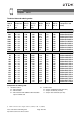
B43504 Compact 105 °C Technical data and ordering codes CR 100 Hz 20 °C µF Case dimensions d×l mm VR = 250 V DC 680 30 × 35 680 35 × 30 820 25 × 55 820 30 × 40 1000 30 × 45 1000 35 × 40 1200 30 × 55 1200 35 × 40 1500 35 × 50 1800 35 × 55 VR = 400 V DC 47 22 × 25 68 22 × 25 82 22 × 30 100 22 × 35 100 25 × 25 120 22 × 35 150 22 × 40 150 30 × 25 180 25 × 40 180 30 × 30 220 25 × 45 220 30 × 35 220 35 × 25 270 25 × 50 270 30 × 40 270 35 × 30 IAC,max 100 Hz 60 °C A IAC,max 100 Hz 85 °C A IAC,R2) 100 Hz 10
B43504 Compact 105 °C Technical data and ordering codes CR 100 Hz 20 °C µF Case dimensions d×l mm VR = 400 V DC 330 25 × 55 330 30 × 45 330 35 × 35 390 30 × 50 390 35 × 40 470 30 × 55 470 35 × 45 560 35 × 50 680 35 × 55 VR = 420 V DC 82 22 × 30 100 22 × 35 100 25 × 30 120 22 × 40 120 25 × 30 150 25 × 35 150 30 × 30 180 25 × 40 180 30 × 30 220 25 × 45 220 30 × 35 270 25 × 55 270 30 × 40 330 30 × 45 330 35 × 35 390 30 × 50 390 35 × 40 470 35 × 45 560 35 × 50 IAC,max 100 Hz 85 °C A IAC,R3) 100 Hz 105 °C
B43504 Compact 105 °C Technical data and ordering codes CR 100 Hz 20 °C µF Case dimensions d×l mm VR = 450 V DC 68 22 × 30 82 22 × 35 100 22 × 35 100 25 × 30 100 30 × 25 120 25 × 35 150 25 × 40 150 30 × 30 150 35 × 25 180 25 × 45 220 25 × 50 220 30 × 40 220 35 × 30 270 30 × 45 270 35 × 35 330 30 × 50 330 35 × 40 390 35 × 45 470 35 × 50 ESRtyp 100 Hz 20 °C mΩ Zmax 10 kHz 20 °C mΩ 1990 1650 1350 1350 1350 1130 900 900 900 750 610 610 610 500 500 410 410 350 290 2350 1950 1600 1600 1600 1330 1070 1070
B43504 Compact 105 °C Useful life1) depending on ambient temperature TA under ripple current operating conditions Frequency factor of permissible ripple current IAC versus frequency f Frequency characteristics of ESR Typical behavior 1) Refer to chapter "General technical information, 5 Useful life" on how to interpret useful life. Please read Cautions and warnings and Important notes at the end of this document.
B43504 Compact 105 °C Impedance Z versus frequency f Typical behavior at 20 °C Please read Cautions and warnings and Important notes at the end of this document.
B43504 Compact 105 °C Cautions and warnings Personal safety The electrolytes used by EPCOS have been optimized both with a view to the intended application and with regard to health and environmental compatibility. They do not contain any solvents that are detrimental to health, e.g. dimethyl formamide (DMF) or dimethyl acetamide (DMAC). Furthermore, some of the high-voltage electrolytes used by EPCOS are self-extinguishing.
B43504 Compact 105 °C Product safety The table below summarizes the safety instructions that must be observed without fail. A detailed description can be found in the relevant sections of chapter "General technical information". Topic Safety information Polarity Make sure that polar capacitors are connected with the right polarity. Reverse voltage Voltages polarity classes should be prevented by connecting a diode. Do not mount the capacitor with the terminals (safety vent) upside down.
B43504 Compact 105 °C Topic Safety information Active flammability Maintenance Avoid overload of the capacitors. Storage Make periodic inspections of the capacitors. Before the inspection, make sure that the power supply is turned off and carefully discharge the electricity of the capacitors. Do not apply any mechanical stress to the capacitor terminals. Do not store capacitors at high temperatures or high humidity. Capacitors should be stored at +5 to +35 °C and a relative humidity of ≤ 75%.
B43504 Compact 105 °C Symbols and terms Symbol English German C CR CS CS,T Cf d dmax ESL ESR ESRf Capacitance Rated capacitance Series capacitance Series capacitance at temperature T Capacitance at frequency f Case diameter, nominal dimension Maximum case diameter Self-inductance Equivalent series resistance Equivalent series resistance at frequency f Equivalent series resistance at temperature T Frequency Current Alternating current (ripple current) Root-mean-square value of alternating current Ripp
B43504 Compact 105 °C Symbol V VF Vop VR VS XC XL Z ZT tan δ λ ε0 εr ω English Voltage Forming voltage Operating voltage Rated voltage, DC voltage Surge voltage Capacitive reactance Inductive reactance Impedance Impedance at temperature T Dissipation factor Failure rate Absolute permittivity Relative permittivity Angular velocity; 2 π f German Spannung Formierspannung Betriebsspannung Nennspannung, Gleichspannung Spitzenspannung Kapazitiver Blindwiderstand Induktiver Blindwiderstand Scheinwiderstan
Important notes The following applies to all products named in this publication: 1. Some parts of this publication contain statements about the suitability of our products for certain areas of application. These statements are based on our knowledge of typical requirements that are often placed on our products in the areas of application concerned.