NTC thermistors for inrush current limiting Leaded and coated disks Series/Type: B57236S0***M0** Date: August 2012 © EPCOS AG 2012. Reproduction, publication and dissemination of this publication, enclosures hereto and the information contained therein without EPCOS' prior express consent is prohibited.
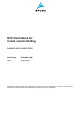
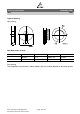
Inrush current limiters B57236S0***M0** ICLs S236 Applications Switch-mode power supplies Dimensional drawing Features Useable in series connections up to 265 VRMS Coated thermistor disk Kinked leads of tinned copper wire Wide resistance range Manufacturer's logo, NTC and resistance value stamped on UL approval (E69802) Options Resistance tolerance <20% and alternative lead configurations available on request Dimensions in mm Approx.
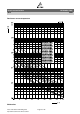
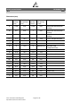
Inrush current limiters B57236S0***M0** ICLs R25 Ω 20 25 50 80 120 S236 Imax (0...65 °C) A 2.8 2.5 1.9 1.6 1.5 Ctest1) 230 V AC µF 300 300 300 400 400 Ctest1) 110 V AC µF 1200 1200 1200 1600 1600 Rmin (@ Imax, 25 °C) Ω 0.284 0.357 0.594 0.861 0.990 ** = Delivery mode 00 = Bulk 51 = Reel packing 1) For details on the capacitance Ctest please refer to "Application notes", chapter 1.6. Please read Cautions and warnings and Important notes at the end of this document.
Inrush current limiters B57236S0***M0** ICLs S236 Reliability data Test Standard Storage in dry heat IEC 60068-2-2 Storage in damp heat, steady state Termal schock Endurance Cyclic endurance Maximum permissible capacitance test Test conditions Storage at upper category temperature T: 170 °C t: 1000 h IEC Temperature of air: 40 °C 60068-2-78 Relative humidity of air: 93% Duration: 21 days IEC Lower test temperature: 55 °C 60068-2-14 t: 30 min Upper test temperature: 170 °C t: 30 min Time to cha
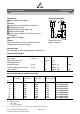
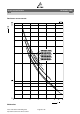
Inrush current limiters B57236S0***M0** ICLs S236 Resistance versus temperature S236 series Please read Cautions and warnings and Important notes at the end of this document.
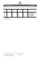
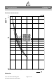
Inrush current limiters B57236S0***M0** ICLs S236 Resistance versus current S236 series Please read Cautions and warnings and Important notes at the end of this document.
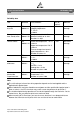
Inrush current limiters B57236S0***M0** ICLs S236 Resistance versus current S236 series Please read Cautions and warnings and Important notes at the end of this document.
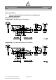
Inrush current limiters B57236S0***M0** ICLs S236 Taping and packing 1 Taping of radial leaded ICL NTC thermistors according to the specified lead spacing Dimensions and tolerances Lead spacing F = 5.0 mm (taping to IEC 60286-2) Lead spacing F = 7.5 mm (taping based on IEC 60286-2) Please read Cautions and warnings and Important notes at the end of this document.
Inrush current limiters B57236S0***M0** ICLs S236 Dimensions (mm) Lead spacing 5 mm Tolerance of lead spacing 5 mm Lead spacing 7.5 mm Tolerance of lead spacing 7.5 mm Remarks w ≤12.0 max. ≥12.0 max. please refer to dimensional drawings th 6.0 max. 7 max. please refer to dimensional drawings d 0.5/0.6 ±0.05 0.8/1.0 ±0.05 please refer to dimensional drawings P0 12.7 ±0.3 12.7 ±0.3 ±1 mm / 20 sprocket holes P1 3.85 ±0.7 8.95 ±0.8 F 5.0 +0.6/ 0.1 7.5 ±0.8 ∆h 0 ±2.
Inrush current limiters B57236S0***M0** ICLs S236 Types of packing Reel packing Reel dimensions (in mm) Reel type d f n w I 360 max. 31 ±1 approx. 45 54 max. II 500 max. 23 ±1 approx. 59 72 max. Bulk packing The components are packed in cardboard boxes, the size of which depends on the order quantity. Please read Cautions and warnings and Important notes at the end of this document.
Inrush current limiters B57236S0***M0** ICLs S236 Mounting instructions 1 Soldering 1.1 Leaded NTC thermistors Leaded thermistors comply with the solderability requirements specified by CECC. When soldering, care must be taken that the NTC thermistors are not damaged by excessive heat. The following maximum temperatures, maximum time spans and minimum distances have to be observed: Dip soldering Iron soldering Bath temperature max. 260 °C max. 360 °C Soldering time max. 4 s max.
Inrush current limiters B57236S0***M0** ICLs S236 Wave soldering Temperature characteristic at component terminal with dual wave soldering 2 Robustness of terminations The leads meet the requirements of IEC 60068-2-21. They may not be bent closer than 4 mm from the solder joint on the thermistor body or from the point at which they leave the feedthroughs. During bending, any mechanical stress at the outlet of the leads must be removed. The bending radius should be at least 0.75 mm.
Inrush current limiters B57236S0***M0** ICLs S236 When subjecting leads to mechanical stress, the following should be observed: Tensile stress on leads During mounting and operation tensile forces on the leads are to be avoided. Bending of leads Bending of the leads directly on the thermistor body is not permissible. A lead may be bent at a minimum distance of twice the wire's diameter +2 mm from the solder joint on the thermistor body.
Inrush current limiters B57236S0***M0** ICLs S236 Cautions and warnings General See "Important notes" at the end of this document. Storage Store thermistors only in original packaging. Do not open the package before storage. Storage conditions in original packaging: storage temperature 25 °C ... +45 °C, relative humidity ≤75% annual mean, maximum 95%, dew precipitation is inadmissible. Avoid contamination of thermistors surface during storage, handling and processing.
Inrush current limiters B57236S0***M0** ICLs S236 Mounting When NTC thermistors are encapsulated with sealing material or overmolded with plastic material, the precautions given in chapter “Mounting instructions”, “Sealing and potting” must be observed. Electrode must not be scratched before/during/after the mounting process. Contacts and housings used for assembly with thermistor have to be clean before mounting. During operation, the inrush current limiters surface temperature can be very high.
Inrush current limiters B57236S0***M0** ICLs S236 Symbols and terms Symbol English German Ctest Cth Test capacitance Heat capacitance Prüfkapazität (elektrisch) Wärmekapazität I Imax Current Maximum current within stated temperature range NTC current Rated current Strom Maximalstrom im angegebenen Temperaturbereich Heißleiter-Strom Nennstrom P25 Pdiss Pel Pmax Maximum power at 25 °C Power dissipation Electrical power Maximum power within stated temperature range Maximale Leistung bei 25 °C Ve
Inrush current limiters B57236S0***M0** ICLs S236 Abbreviations / Notes Symbol English * To be replaced by a number in ordering Platzhalter für Zahl im Bestellnummerncodes, type designations etc. code oder für die Typenbezeichnung. + To be replaced by a letter. Platzhalter für einen Buchstaben. All dimensions are given in mm. Alle Maße sind in mm angegeben. The commas used in numerical values denote decimal points. Verwendete Kommas in Zahlenwerten bezeichnen Dezimalpunkte.
Important notes The following applies to all products named in this publication: 1. Some parts of this publication contain statements about the suitability of our products for certain areas of application. These statements are based on our knowledge of typical requirements that are often placed on our products in the areas of application concerned.