PTC thermistors as limit temperature sensors Motor protection, single sensors Series/Type: B59100 Date: December 2009 © EPCOS AG 2009. Reproduction, publication and dissemination of this publication, enclosures hereto and the information contained therein without EPCOS' prior express consent is prohibited.
Sensors Motor protection, single sensors Applications Thermal protection of winding in electric motors Limit temperature monitoring Features Thermistor pellet with insulating encapsulation Low-resistance type, steep R/T curve Silver-plated and PTFE-insulated AWG 26 litz wires Extremely fast response due to small dimensions Characteristics for sensing temperatures Tsense = 90 up to 160 °C conform with DIN 44081 Color coding of litz wires to DIN 44081 UL approval to UL 1434 (file number E69802) RoHS-compatib
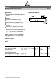
Sensors Motor protection, single sensors M1100 Electrical specifications and ordering codes Tsense °C ∆T = ±5 K 60 70 80 90 100 110 120 130 140 145 150 155 160 ∆T = ±7 K 170 180 R (Tsense ∆T) (VPTC ≤ 2.5 V) Ω R (Tsense + ∆T) (VPTC ≤ 2.5 V) Ω R (Tsense + 15 K) (VPTC ≤ 7.5 V) Ω R (Tsense + 23 K) (VPTC ≤ 2.
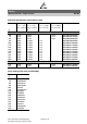
Sensors Motor protection, single sensors M1100 Reliability data Test Electrical endurance, cycling Electrical endurance, constant Damp heat Standard IEC 60738-1 Rapid change of temperature IEC 60738-1 Vibration IEC 60738-1 IEC 60738-1 IEC 60738-1 Please read Cautions and warnings and Important notes at the end of this document.
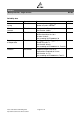
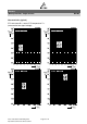
Sensors Motor protection, single sensors M1100 Characteristics (typical) PTC resistance RPTC versus PTC temperature TPTC (measured at low signal voltage) Please read Cautions and warnings and Important notes at the end of this document.
Sensors Motor protection, single sensors M1100 Characteristics (typical) PTC resistance RPTC versus PTC temperature TPTC (measured at low signal voltage) Please read Cautions and warnings and Important notes at the end of this document.
Sensors Motor protection, single sensors M1100 Cautions and warnings General EPCOS thermistors are designed for specific applications and should not be used for purposes not identified in our specifications, application notes and data books unless otherwise agreed with EPCOS during the design-in-phase. Ensure suitability of thermistor through reliability testing during the design-in phase. The thermistors should be evaluated taking into consideration worst-case conditions.
Sensors Motor protection, single sensors M1100 Mounting Electrode must not be scratched before/during/after the mounting process. Contacts and housing used for assembly with thermistor have to be clean before mounting. Especially grease or oil must be removed. When PTC thermistors are encapsulated with sealing material, the precautions given in chapter "Mounting instructions", "Sealing and potting" must be observed.
Sensors Motor protection, single sensors M1100 Symbols and terms A Cth f I Imax IR IPTC Ir Ir,oil Ir,air IRMS IS ISmax LCT N Nc Nf P P25 Pel Pdiss Rmin RR ∆RR RP RPTC Rref RS R25 R25,match ∆R25 T t TA ta TC Area Heat capacity Frequency Current Maximum current Rated current PTC current Residual currrent Residual currrent in oil (for level sensors) Residual currrent in air (for level sensors) Root-mean-square value of current Switching current Maximum switching current Lower category temperature Number (in
Sensors Motor protection, single sensors M1100 tE TR Tsense Top TPTC tR Tref TRmin tS Tsurf UCT V or Vel VRMS VBD Vins Vlink,max Vmax Vmax,dyn Vmeas Vmeas,max VR VPTC Settling time (for level sensors) Rated temperature Sensing temperature Operating temperature PTC temperature Response time Reference temperature Temperature at minimum resistance Switching time Surface temperature Upper category temperature Voltage (with subscript only for distinction from volume) Root-mean-square value of voltage Breakdow
Important notes The following applies to all products named in this publication: 1. Some parts of this publication contain statements about the suitability of our products for certain areas of application. These statements are based on our knowledge of typical requirements that are often placed on our products in the areas of application concerned.