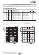
Power line chokes Current-compensated frame core double chokes 300 V AC, 0.7 … 2.3 A, 10 … 100 mH, +40 °C Series/Type: B82733F/V Date: May 2015 a~í~=pÜÉÉí EPCOS AG 2015. Reproduction, publication and dissemination of this publication, enclosures hereto and the information contained therein without EPCOS' prior express consent is prohibited. EPCOS AG is a TDK Group Company.
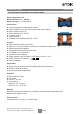
Power line chokes B82733F/V Current-compensated frame core double chokes Rated voltage 300 V AC Rated inductance 10 ... 100 mH Rated current 0.7 ... 2.3 A / +40 °C Construction ■ ■ ■ ■ ■ ■ ■ Current-compensated frame double chokes Closed magnetic circuit with frame construction made of ferrite Epoxy coating (UL94 V-0) Plastic coil former (UL94 V-0) 2-section winding Sector winding Clearance and creepage distances >4 mm Features ■ ■ ■ ■ ■ ■ ■ ■ ■ High inductance with low resistance Approx.
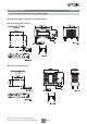
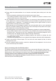
Power line chokes B82733F/V Current-compensated frame core double chokes Dimensional drawing and layout recommendation B82733F (horizontal version) B82733V (vertical version) Please read Cautions and warnings and Important notes at the end of this document.
Power line chokes B82733F/V Current-compensated frame core double chokes C Technical data and measuring conditions Rated voltage VR 300 V AC (50/60 Hz) Test voltage Vtest 2000 V AC, 2 s (line/line) Rated temperature TR +40 qC Rated current IR Referred to 50 Hz and rated temperature Rated inductance LR Measured with Agilent 4284A at 10 kHz, 0.1 mA, +20 °C. Inductance is specified per winding.
Power line chokes B82733F/V Current-compensated frame core double chokes Characteristics and ordering codes IR LR Lstray,typ Rtyp Ordering code Approvals A mH PH m: horizontal vertical 0.7 100 2100 1810 B82733F2701B001 B82733V2701B001 0.9 68 1440 1100 B82733F2901B001 B82733V2901B001 1.1 47 970 804 B82733F2112B001 B82733V2112B001 1.2 39 800 696 B82733F2122B001 B82733V2122B001 1.4 27 550 440 B82733F2142B001 B82733V2142B001 1.
Cautions and warnings ■ Please note the recommendations in our Inductors data book (latest edition) and in the data sheets. – Particular attention should be paid to the derating curves given there. – The soldering conditions should also be observed. Temperatures quoted in relation to wave soldering refer to the pin, not the housing.
Important notes The following applies to all products named in this publication: 1. Some parts of this publication contain statements about the suitability of our products for certain areas of application. These statements are based on our knowledge of typical requirements that are often placed on our products in the areas of application concerned.