Data and signal line chokes Common-mode chokes, ring core 4.7 … 50 mH, 100 … 600 mA, 60 °C Series/Type: B82792C0 %BUB 4IFFU April 2008 Date: EPCOS AG 2015. Reproduction, publication and dissemination of this publication, enclosures hereto and the information contained therein without EPCOS' prior express consent is prohibited. EPCOS AG is a TDK Group Company.
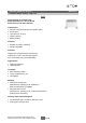
Data and signal line chokes B82792C0 Common-mode chokes, ring core Rated voltage 42 V AC/80 V DC Rated inductance 4.7 mH to 50 mH Rated current 100 mA to 600 mA Construction ■ ■ ■ ■ ■ Current-compensated ring core double choke Ferrite core LCP case (UL 94 V-0) Silicone potting Bifilar winding Features ■ Suitable for reflow soldering ■ RoHS-compatible Function Suppression of asymmetrical interference coupled in on lines, whereas data signals up to some MHz can pass unaffectedly.
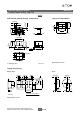
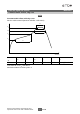
Data and signal line chokes B82792C0 Common-mode chokes, ring core Dimensional drawing and pin configuration Layout recommendation 4 5 3 6 2 7 1 8 3 x 2.5 4 5 1.6 3 x 2.5±0.1 1.5 min. 1) _ 0.051) 0.6 +0.1 2.5±0.2 9 15 1 8 IND0165-V 0.4 +0.1 _ 0.05 1) 7.3 max. 2 ...8 11.5 max. 14±0.4 10.5 max. 0.1 Marking 1) Soldering area IND0164-H-E Dimensions in mm Taping and packing Blister tape Reel 2±0.1 8.1 13±0.25 _2 330 +0 24±0.3 1.6±0.1 1.75±0.1 30.4 max. 11.5±0.1 4±0.
Data and signal line chokes B82792C0 Common-mode chokes, ring core Technical data and measuring conditions Rated voltage VR 42 V AC (50/60 Hz) / 80 V DC Rated temperature TR 60 °C Rated current IR Referred to 50 Hz and rated temperature Rated inductance LR Measured with Agilent 4284A at 10 kHz, 50 mV, 20 °C Inductance is specified per winding.
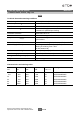
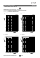
Data and signal line chokes B82792C0 Common-mode chokes, ring core Insertion loss α (typical values at |Z| = 50 Ω, 20 °C) asymmetrical, all branches in parallel (common mode) symmetrical (differential mode) LR = 6.8 mH LR = 4.
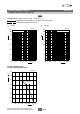
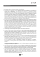
Data and signal line chokes B82792C0 Common-mode chokes, ring core Insertion loss α (typical values at |Z| = 50 Ω, 20 °C) asymmetrical, all branches in parallel (common mode) symmetrical (differential mode) LR = 50 mH LR = 33 mH IND0170-T 60 dB B82792C0336N365 α 50 α 50 40 40 30 30 20 20 10 10 0 4 10 10 5 10 6 10 7 0 4 10 10 8 Hz 10 9 f Current derating Iop/IR versus ambient temperature IND0681-C-E 1.4 Iop IR 1.2 1.0 TR = 60 ˚C 0.8 0.6 0.4 0.
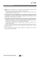
Data and signal line chokes B82792C0 Common-mode chokes, ring core Recommended reflow soldering curve Pb-free solder material (based on JEDEC J-STD 020C) t3 T4 T3 t2 T2 T1 t1 IND0814-F T1 T2 T3 T4 t1 t2 t3 °C °C °C °C s s s 150 200 217 250 < 110 < 90 < 30 @ T4 –5 °C Time from 25 °C to T4: max 300 s Maximal numbers of reflow cycles: 3 Please read Cautions and warnings and Important notes at the end of this document.
Cautions and warnings ■ Please note the recommendations in our Inductors data book (latest edition) and in the data sheets. – Particular attention should be paid to the derating curves given there. – The soldering conditions should also be observed. Temperatures quoted in relation to wave soldering refer to the pin, not the housing.
Important notes The following applies to all products named in this publication: 1. Some parts of this publication contain statements about the suitability of our products for certain areas of application. These statements are based on our knowledge of typical requirements that are often placed on our products in the areas of application concerned.