
Information


52
Catalog 82181 Dimensions are in inches and Dimensions are shown for USA: 1-800-522-6752 South America: 55-11-2103-6000
Revised 2-07 millimeters unless otherwise reference purposes only. Canada: 1-905-470-4425 Hong Kong: 852-2735-1628
specified. Values in brackets Specifications subject Mexico: 01-800-733-8926 Japan: 81-44-844-8013
www.tycoelectronics.com are metric equivalents. to change. C. America: 52-55-1106-0803 UK: 44-8706-080-208
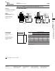
.062 [1.57] Commercial Pin and Socket Connectors (Continued)
AMP
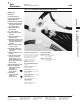
Soft Shell
Pin and Socket Connectors
.062 [1.57] Commercial Pin and Socket Connectors
.145 [3.68] Centerline
High Density
Performance Characteristics
(Continued)
Maximum Current—Maximum cur-
rent rating of .062 Commercial Pin and
Socket connectors is limited by the
maximum operating temperature of the
housings which is 105°C including the
temperature rise of the contacts which is
a maximum of 30°C. There are several
variables which have a direct effect on
this maximum current-carrying capabil-
ity for a given connector and must be
considered for each application. These
variables are:
Wire Size—Larger wire will carry
more current since it has less internal
resistance to current flow and thus gen-
erates less heat. Longer wire lengths
also enhance current-carrying capabili-
ties since the wire conducts heat away
from the connector.
Connector Size—In general, the more
circuits in a connector, the less current
can be carried.
Ambient Temperature—The higher
the ambient temperature, the less cur-
rent can be carried in any given connec-
tor.
Related Product Data
Product Specification —
108-1037
Application Specification —
114-1013
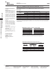
Current Rating Verification for 30°C Maximum Temperature Rise 100% Energized
Wire-to-Wire
.062 Commercial Pin and Socket Connectors Calculated Current Table
Number of
Wire Gauge
Circuits
18 20 22 24
27.00 6.00 5.00 4.00
37.00 6.00 5.00 4.00
46.00 6.00 5.00 4.00
46.00 5.00 4.00 3.00
66.00 5.00 4.00 3.00
95.00 4.00 4.00 3.00
Values are based on initial Temperature Rise versus Current Testing and are intended to be a guide in the selection of
a connector family. All applications should be tested by the end user. The values listed are per circuit for fully loaded
housings being 100% energized. Note: All combinations were not tested, and this chart contains interpolated and
extrapolated values.
Minimum Wire Lengths for T-Rise vs. Current Testing
AWG Min. Length (in.) AWG Min. Length (in.)
30 2.6 18 9.4
28 3.2 16 11.3
26 4.1 14 13.7
24 5.1 12 16.4
20 7.8 10 19.3
Note: If wire lengths used are less than those listed above, the current-carry-
ing ability of the system will be reduced due to less heat being conducted
away from the connector. The customer should fully test all applications.
Termination Resistance/Contact Crimp Tensile Force
Termination
Contact
Resistance
Crimp
Wire Size
Test Resistance
Tensile Force
AWG mm
2
Current Milliohms
Force (Min.)
(Amps) (Max. Init.)
lbs. N
24 0.2 1.5 3.50 10 44.5
22 0.3–0.4 3.0 3.50 10 44.5
20 0.5–0.6 4.5 3.00 13 57.8
18 0.8–0.9 6.0 3.00 14 62.3
Note: This is the total resistance between wire crimps of a mated pin
and socket.