
Information

184
Catalog 82181 Dimensions are in inches and Dimensions are shown for USA: 1-800-522-6752 South America: 55-11-2103-6000
Revised 2-07 millimeters unless otherwise reference purposes only. Canada: 1-905-470-4425 Hong Kong: 852-2735-1628
specified. Values in brackets Specifications subject Mexico: 01-800-733-8926 Japan: 81-44-844-8013
www.tycoelectronics.com are metric equivalents. to change. C. America: 52-55-1106-0803 UK: 44-8706-080-208
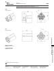
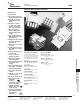
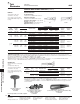
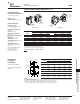
Universal MATE-N-LOK II Connectors (Continued)
AMP
Soft Shell
Pin and Socket Connectors
Universal MATE-N-LOK II Connectors
.250 [6.35] Centerline
Standard Density
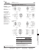
Performance
Characteristics (Continued)
Maximum Current—Maximum cur-
rent rating of Universal MATE-N-LOK II
connectors is limited by the maximum
operating temperature of the housings
which is 120°C including the tempera-
ture rise of the contacts which is a maxi-
mum of 30°C. There are several
variables which have a direct effect on
this maximum current-carrying capabil-
ity for a given connector and must be
considered for each application. These
variables are:
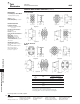
Wire Size—Larger diameter wire will
carry more current since it has less
internal resistance to current flow and
thus generates less heat. Longer wire
lengths also enhance current carrying
capabilities since the wire conducts heat
away from the connector.
Connector Size—In general, the more
circuits in a connector, the less current
can be carried.
Ambient Temperature—The higher
the ambient temperature, the less current
can be carried in any given connector.
Universal MATE-N-LOK II connectors
also will withstand the following tests:
Vibration—10-55-10 cycles per
minute at .06 inch total excursion
Physical Shock—18 drops,
50 g sawtooth at 10 milliseconds
Housing Panel Retention—75 lb. min.
Housing Lock Strength—35 lb. min.
Thermal Shock— -55°C to +85°C
Temperature-Humidity Cycling—
25°C to 65°C at 95 RH
Corrosion—48 hr. at 5% salt
concentration
Related Product Data
Product Specification
108-1090 Universal MATE-N-LOK II
Connectors
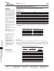
Termination
Contact
Resistance
Crimp
Wire Size
Test Resistance
Tensile Force
AWG mm
2
Current Milliohms
Force (Min.)
(Amps) (Max. Init.)
lbs. N
30 .05 — — 1.5 7
28 .08 — — 3 13
26 .12 — — 5 22
24 .2 1.5 3.50 7 31
22 .3 3 3.50 12 53
20 .5 4.5 3.00 17 66
18 .8 6 3.00 30 133
16 1.2 8 2.75 45 200
14 2.0 10 2.75 50 222
12 3.0 — — 60 267
10 5.0 — — 70 311
Note: This is the total resistance between wire crimps of a mated pin and
socket.
Current Rating Verification for 30°C Maximum Temperature Rise 100% Energized
Wire-to-Wire
Minimum Wire Lengths for T-Rise vs. Current Testing
AWG Min. Length (in.) AWG Min. Length (in.)
30 2.6 18 9.4
28 3.2 16 11.3
26 4.1 14 13.7
24 5.1 12 16.4
20 7.8 10 19.3
Note: If wire lengths used are less than those listed above, the current carry-
ing ability of the system will be reduced due to less heat being conducted
away from the connector. The customer should fully test all applications.
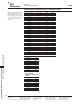
Calculated Current Table
Number of
Wire Gauge
Circuits
10 12 14 16 18 20 22 24 26 30
2 19.00 18.00 17.00 14.50 13.00 10.00 8.00 6.50 5.50 3.50
3 17.50 16.50 15.50 13.00 12.00 9.00 7.50 6.00 5.00 3.00
4 16.50 15.50 15.00 12.50 11.00 8.50 7.00 5.50 4.50 3.00
5 16.00 15.00 14.00 12.00 10.50 8.00 6.50 5.50 4.50 3.00
6 Matrix 15.00 14.00 13.00 11.00 9.50 7.50 6.00 5.00 4.00 2.50
8 14.50 14.00 13.00 10.50 9.50 7.50 6.00 5.00 4.00 2.50
9 13.50 12.50 11.50 9.50 8.50 6.50 5.50 4.50 3.50 2.00
10 14.00 13.00 12.50 10.00 9.00 7.00 5.50 4.50 3.50 2.50
12 12.50 12.00 11.00 9.00 8.00 6.00 5.00 4.00 3.00 2.00
15 12.00 11.50 10.00 8.50 7.50 6.00 4.50 4.00 3.00 2.00
Values are based on initial Temperature Rise versus Current Testing and are intended to be a guide in the selection
of a connector family. All applications should be tested by the end user. The values listed are per circuit for fully
loaded housings being 100% energized. Note: All combinations were not tested, and this chart contains interpolated
and extrapolated values.
Wire-to-Board
Due to the vast differences in trace geometry and printed circuit board configurations, we are unable to provide a
separate current carrying chart for our printed circuit board header products. However, the above Wire-to-Wire charts
may be used as a guideline for headers if the trace width and thickness is equal to the listed wire gauge. For vertical
headers, only 95% of the Wire-to-Wire value should be used. For right-angle headers, only 75% of the Wire-to-Wire
value should be used. The chart values are only a tool for connector selection and will require the customer to fully
test their application.
Termination Resistance/Contact Crimp Tensile Force