
Information


A STEP AHEAD
Common Contact System Technical Manual
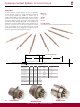
SOLID STYLE
INDENTER CRIMP
CROSS SECTION ACROSS AXIS
CORRECT
INSULATION
GAP
(IF REQUIRED)
CONDUCTOR
STRANDS VISIBLE
PROPER
INDENTS
ACCEPTABLE CRIMP
CONDUCTOR
STRANDS
NOT VISIBLE
FLAYED
WIRE
BIRDCAGE
UNACCEPTABLE CRIMP
CRIMP INSPECTION
Crimping tools are, in some case, more expensive than soldering
tools, but this is more than off-set by the lower total installation
and maintenance costs resulting from the crimping operation.
However, controls are required to make sure first, that the
operator uses the proper crimping tools designed for the type
and size contact being crimped, and then, that the pin or socket
is properly inserted into the tool. The wire must be stripped of
insulation and fully inserted into the contact. The usual procedure
is to insert the wire into the open end of the contact, then close
the crimping tool, thus crimping the wall of the contact into the
wire at several points around the circumference.
When completed, correct assembly can be checked visually. The
removed insulation should expose a conductor length that will
pass beyond the inspection hole in the contact and still reveal
.025 - .100 (.063 - 2.54) of conductor between the contact and
the insulation on the wire. The operator and inspector can thus
check for:
1) Damaged wire strands.
2) Missing wire strands.
3) Wire strands not entering the contact barrel.
4) Wire not inserted to the proper depth in the contact.
When the correct tool is used for crimping, a good termination
is assured.
For more detailed crimp dimensions please request a factory
drawing. For Stamped and Formed Style see 0425 -*** - 0000.
For Solid Style see 0425-205-0000.
COMMON TOOLING
By selecting the Deutsch common contact system, only one style
of tool is needed to remove wires. In designs like the DT and DTM
Series connectors, even this tool is eliminated. Hand crimp tools
are used to crimp different types of contacts to the wire end.
For automation, semi and full automatic crimping equipment
is available that will process thousands of wire terminations per
hour.
COMMON PROCESSING
Using the Deutsch contact means that the way an O.E.M. supplier
attaches a wire to this terminus never varies. This procedural
standard allows harness assemblers to become highly proficient
in terminating Deutsch connectors.
SOLID TYPE
.025 - .100 (.063 - 2.54)
A
A
4
A
A
B
B
PIN / SOCKET
SIDE VIEW
STAMPED AND FORMED TYPE
VIEW B-B
INSULATOR CRIMP
VIEW A-A
CONDUCTOR CRIMP
CRIMP HEIGHT
MICROMETER
BLADE DIMENSIONS
CRIMP HEIGHT
CRIMP WIDTH
.060 in. (1.50 mm)
.015 in. (0.40 mm)
.100 IN. (2.54 mm) MIN.