
Information


A STEP AHEAD
6
Common Contact System Technical Manual
** = Plating Codes Consult factory for custom finish needs.
For 12 Size, see 0425-041-0000 and 0425-208-0000
For 16 Size, see 0425-039-0000, 0425-059-0000, and 0425-203-0000
For 20 Size, see 0425-059-0000 and 0425-207-0000
STAMPED AND FORMED
Deutsch Stamped and Formed contacts are designed for use
where wire termination costs are of primary concern without
sacrificing reliability of electrical circuits.
DESIGN AND MATERIALS SELECTION
Deutsch engineers have combined the process of superior
material selection with outstanding mechanical Cad-Cam
Designs to present stamped and formed contacts that exceed the
demands of today’s truck and off-highway electrical systems.
The selection of copper alloys, finished after forming with nickel
plating provides superior durability, performance, corrosion and
oxidation resistance.
To achieve air-tight crimps that eliminate the need to solder
after wire terminations, Deutsch engineers have specified that
the core-wing ends be formed in the direction of the crimp,
thus assuring resistance to crimp relaxation and displacement of
metal, crimp after crimp.
Deutsch socket tines are protected by a closed entry stainless
steel sleeve, to ensure controlled contact pressure for maximum
conductivity with minimum surface wear.
In keeping with the Deutsch commitment to total quality, all
stamped and formed contacts are manufactured using SPC
controls and are subjected to extensive programs of rigid testing,
including field performance feedback.
FEATURES BENEFITS
Stainless Steel Socket Sleeve Provides closed entry design preventing probe damage.
Contact Tines are in Socket Member, Not Pin Terminal contact points are protected from handling and assembly damage.
No Lances / Tangs Contact retention is designed in the connector body, eliminating retention problems during handling and rework.
Bullet (rounded) Pin Nose Prevents mismating and bent pins.
Nickel Plating Reduces oxidations, thus improving conductivity performance.
Plated After Forming No base metal is exposed to corrosion.
Optional Gold Plating Available for dry circuit application.
No Individual Wire Seal Grommets Wire seals are designed as an integral component of the connector, thus reducing wire terminating costs.
Pre-Bent or Compound Arch Core Wings Provides an air-tight crimp joint.
Improved Die Stop Gap Allows application die to position wire for proper crimp length.
Off-Set Configuration Provides center wire alignment between conductor and insulation.
Copper Alloy Materials Prevents material relaxation over time, providing reliable crimp joints and increased durability.
SIZE
20
20
20
20
16
16
16
16
16
16
16
16
12
12
PIN SOCKET
WIRE
INSULATION
O.D. RANGE
RECOMMENDED
STRIP LENGTH
INCHES (mm)
MIN CONT.
RETENTION
LBS (N)
MAX RATED AMPS
AT 125
0
C
CONTINUOUS
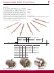
Stamped & Formed Contacts
STAMPED & FORMED CONTACT
PART NUMBERS
1060-20-01**
1060-20-02**
N/A
1060-20-06**
1060-14-01**
1060-14-10**
1060-16-01**
1060-16-06**
1060-16-07**
1060-16-09**
1060-16-12**
N/A
1060-12-01**
1060-12-02**
1062-20-01**
1062-20-02**
1062-20-03**
1062-20-06**
1062-14-01**
1062-14-10**
1062-16-01**
1062-16-06**
1062-16-07**
1062-16-09**
1062-16-12**
1062-16-14**
1062-12-01**
1062-12-02**
20 - 01
20 - 02
20 - 03
20 - 06
14 - 16
14 - 16
16 - 18
0.5 - 1.0
0.75 - 2.0
16 - 18
1.0 - 2.5
14 - 16
12 - 14
10 - 12
16 - 22
(1.5 - 0.35)
16 - 22
(1.5 - 0.35)
16 - 22
(1.5 - 0.35)
14 -16
(2.5 - 1.0)
14 - 18
(2.0 - .75)
14 - 16
(2.0 - .75)
14 - 18
(2.0 - .75)
16 - 20
(1.0 - 0.50)
14 -18
(2.0 - .75)
14 -18
(2.0 - .75)
12 -16
(2.5 - 1.0)
12 - 16
(2.5 - 1.0)
12 - 14
(4.0 - 2.0)
10 - 12
(6.0 - 4.0)
.075 - .125
(1.91 - 3.15)
.051 - .085
(1.30 - 2.16)
.075 - .125
(1.91 - 3.15)
.075 - .125
(1.91 - 3.15)
.095 - .150
(2.41 - 3.81)
.095 - .150
(2.41 - 3.81)
.075 - .140
(1.91 - 3.55)
.055 - .100
(1.40 - 2.54)
.075 - .140
(1.91 - 3.55)
.075 - .140
(1.91 - 3.55)
.075 - .140
(1.91 - 3.55)
.075 - .140
(1.91 - 3.55)
.113 - .176
(2.87 - 4.47)
.140 - .204
(3.56 - 5.18)
.150 - .200
(3.81 - 5.08)
.150 - .200
(3.81 - 5.08)
.150 - .200
(3.81 - 5.08)
.150 - .200
(3.81 - 5.08)
.150 - .200
(3.81 - 5.08)
.150 - .200
(3.81 - 5.08)
.150 - .200
(3.81 - 5.08)
.150 - .200
(3.81 - 5.08)
.150 - .200
(3.81 - 5.08)
.150 - .200
(3.81 - 5.08)
.175 - .225
(4.45 - 5.72)
.175 - .225
(4.45 - 5.72)
.225 - .275
(5.72 - 6.991)
.225 - .275
(5.72 - 6.99)
20
(89)
20
(89)
20
(89)
20
(89)
25
(111)
25
(111)
25
(111)
25
(111)
25
(111)
25
(111)
25
(111)
25
(111)
30
(134)
30
(134)
7.5
7.5
7.5
7.5
13
13
13
13
13
13
13
13
25
25
CARRIER
STRIP
IDENTIFICATION
WIRE SIZE
AWG (mm
2
)