
Information


A STEP AHEAD
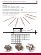
SOLID CONTACTS
Universal Hand Crimp tool
HDT - 48 - 00
For size 20, 16 & 12 contacts
1) Strip specified length of insulation from wire
2) Raise selector knob and rotate until arrow is aligned with
wire size to be crimped.
3) Loosen lock nut, turn adjusting screw in until it stops.
4) Insert contact, turn adjusting screw counter clockwise out
until contact is flush with indenter cover. Tighten lock nut.
5) Insert wire in contact, contact must be centered between
indenters, close handles until handle contacts the stop.
6) Release handles and remove crimped contact.
7) Inspect terminal to insure that all strands are in crimp barrel.
Note; tool must be readjusted for each type/size of contact or
wire.
Common Contact System Technical Manual
7
CONTACTS AND APPLICATION DATA
Solid Contacts
* Deutsch can only warrant electrical performance when proper parts, procedures and tooling from approved Crimp Termination Information Drawings are Used.
* See Information Drawing 0425-205-0000. Consult factory for alternate finishes.
SIZE
SOLID CONTACT
PART NUMBERS
WIRE SIZE
AWG (mm
2
)
RECOMMENDED
STRIP LENGTH
INCHES (mm)
MIN CONTACT
RETENTION
LBS (N)
REF CRIMP
TENSILE
LBS (N)
MAX RATED
AMPS AT 125
0
C
CONTINUOUS
PIN SOCKET
20
20
16
16
12
8
4
20
(0.50)
.156-.218
(3.96 - 5.54)
20
(89)
20
(89)
7.5
14
(2.0)
16-20
(1.0 - 0.50)
12-14
(3.0 - 2.0)
.250 - .312
(6.35 - 7.92)
.250 - .312
(6.35 - 7.92)
.222 - .284
(5.64 - 7.21)
6
(13.0)
8-10
(8.0 - 5.0)
.430-.492
(10.92-12.50)
.430 - .492
(10.92 - 12.50)
25
(111)
25
(111)
30
(134)
70
(311)
35-20
(156-89)
75-70
(334 - 311)
13
13
25
35
(156)
35
(156)
300
(1334)
100
125-90
(556-400)
60
0460-202-20** 0462-201-20**
0460-010-20** 0462-005-20**
0460-202-16** 0462-201-16**
0460-215-16** 0462-209-16**
0460-204-12** 0462-203-12**
0460-204-08** 0462-203-08**
0460-204-04** 0462-203-04**
*
16-18
(1.0 - 0.75)
.156-.218
(3.96 - 5.54)
20
(89)
20
(89)
7.5