
Data Sheet


Ultra Precision Wire-Wound Resistors
Type UPW Series
Literature No. 1773299
Issued: 04-05
Dimensions are shown for
reference purposes only.
Dimensions are in millimetres
unless otherwise specified.
Specifications subject to
change.
www.tycoelectronics.com
passives.tycoelectronics.com
Key Features
■ Custom weld tabs and copper
weld leads ensure a good
mechanical and electrical
connection between the
element and the lead wires.
Protection is given to the
windings by means of a layer
of silicone RTV rubber. This
allows movement of the
windings during temperature
cycling due to loads and
to varying ambient
temperatures. Outer protec-
tion is given by means of a
hot transfer moulded epoxy
compound which ensures an
airtight coating with no
trapped air.
■ Superior quality wire-wound
resistors with very low
selection tolerances and
temperature coefficients
down to 1 ppm. 3 case sizes
are available. T/C, ratio and
pair matching is available
and customer specifications
are welcome. These compo-
nents exhibit high stability
under load and severe
environmental conditions.
Type UPW Series
The resistive element is wire wound
onto a moulded high temperature
plastic bobbin with a central former.
The direction of winding is reversed
part way through the winding, giving
very low values of inductance.
These Neohm resistors use bobbin
assemblies with flattened lead ends,
providing high resistance to pull,
vibration and torsional forces during
handling, assembly and life.
Characteristics -
Electrical
UPW15 UPW25 UPW30 UPW50
Rated Power @ 125°C (W) 0.125 0.25 0.3 0.5
Derate to zero at 145°C
Resistance Range (Ohms) Min R10 R10 R10 R10
Max 300K 1M0 1M0 2M0
Tolerance (%) 0.005 0.01 0.02 0.05 0.1 0.2 0.5 1
Code Letter E L P W B A D F
Limiting Element Voltage (V)
150 300 150 400
Temperature Coefficient (ppm/°C) Typ. ± 3 (0°C to +85°C)
Max. ± 5 (-55°C to +125°C) ± 1 available on request
Operating Temperature Range (°C) -55 to +145
Long Term Stability (Load) < 50 ppm @ 10,000 hrs
< 100ppm @ 26,000 hrs
Thermal EMF < 0.2 µ V /°C
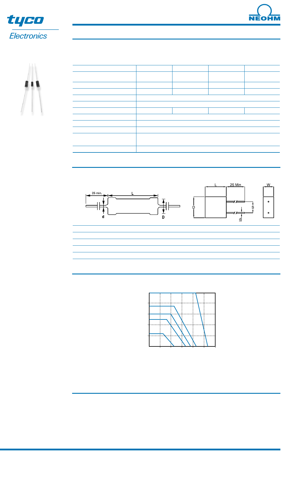
Dimensions
Style A Style B
Type Style L ± 0.4 D ± 0.4 W ± 0.5 s ± 0.2 d nom
UPW15 A 6.35 3.18 - - 0.64
UPW25 A 9.53 4.75 - - 0.64
UPW30 B 7.62 7.62 3.18 3.81 0.64
UPW50 A 12.7 6.35 - - 0.81
Derating Curve
40 60 80 100 120 140 160
100
80
60
40
20
0
Percent Rated Power
Ambient Temperature (°C)
UPW Series resistors must be derated for tolerances below 0.1%. Use the graph to select tolerance versus operating
temperature to determine the percentage rated power for operation.
No derating is required for operation below 20 °C.
1%, 0.5%, 0.2%, 0.1%
0.05%
0.02%
0.01%
0.005%
Mounting
The resistors are suitable for processing on automatic insertion equipment and cutting and bending machines.