
Datasheet


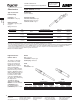

Standard Sex Connectors (Receptacles accept pin contacts, Plugs accept socket contacts)
Arrangement
Square Flange Receptacle
Shell No. of
Keying With Threaded With Mounting Plug
Size Positions
Inserts
1
Holes
13-7 A 211401-4 211401-1 211399-1
17-9 A 211767-2 211767-1 211766-1
23-19
A 211771-2 211771-1 211770-2
B — 213870-1 213853-1
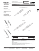
Reverse Sex Connectors (Receptacles accept socket contacts, Plugs accept pin contacts)
Arrangement Square Flange Receptacle
Free-Hanging
Shell No. of
Keying With Threaded With Mounting
Receptacle
Plug
Size Positions
Inserts
1
Holes
13-7 A 211398-4 211398-1 211398-2 211400-1
17-9
A — 211769-1 211769-3 211768-1
B — 796439-2 — 796450-1
23-19
A — 211773-1 — 211772-1
B — 213868-1 — 213852-1
1
Four 4-40 threaded inserts per receptacle.
Key Style “A” is the Standard 5 Locating Key arrangement. Key Style “B” is the 4 Locating Key arrangement.
CPC
Series 1
Circular Connectors for
Commercial Signal and Power Applications
11
Catalog 82021 Dimensions are in inches and Dimensions are shown for USA: 1-800-522-6752 South America: 55-11-2103-6000
Revised 7-06 millimeters unless otherwise reference purposes only. Canada: 1-905-470-4425 Hong Kong: 852-2735-1628
specified. Values in brackets Specifications subject Mexico: 52-55-1106-0800 Japan: 81-44-844-8013
www.tycoelectronics.com are metric equivalents. to change. C. America: 57-1-254-4444 UK: 44-208-420-8341
Circular Plastic Connectors, Series 1, VDE Tested
Note: All part numbers
are RoHS Compliant.
Keying
A—Standard Configuration: 5 Keys
B—Optional Configuration: 4 Keys
CPC Connectors, Series 1,
for Cable or Panel Mount
(Accepts Type III+, High-
Current Power, Type II and
Subminiature Coax
Contacts)
n Designed to meet
requirements of VDE as
shown in DIN
Specification 57627
n Recognized under the
Component Program of
Underwriters
Laboratories Inc.
for 600 VAC and
600 VDC service,
File No. E28476
n Certified by Canadian
Standards
Association,
File No. LR 7189
Listed part numbers are for
connectors only;
contacts
must be ordered separately.
Material
Housing—Thermoplastic, 94V-0 rated,
black
Related Product Data
Contacts—Pages 16-22
Contact Arrangement—Page 23
Component Dimensions—Page 24*
Accessories—Pages 37-41, 51-53
Performance Characteristics—
Page 6
Application Tooling—Pages 75-78
Technical Documents—Page 79
Replacement Coupling Rings
Shell Size Part No.
13 213813-1
17 213810-1
23 213812-1
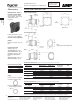
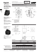
R
R
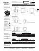
Plug
*M Max.
*N Max.
*Thread Size
(See chart)
*J Dia.
Panel Cutout
*L Max.
*K
Max.
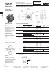
Free-Hanging Receptacle
*Panel Thk.
.125
[3.18]
Max.
*E Max.
*A
Max.
*A
Max.
*Thread Size
(See chart)
*Thread Size
(See chart)
*E Max.
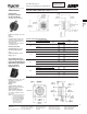
*Note:
See page 24 for callout dimensions
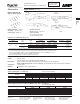
*D
±.010
[±0.25]
*B
±.015
[±0.38]
*B
±.015
[±0.38]
*C
±.010
[±0.25]
*C
±.010
[±0.25]
*D
±.010
[±0.25]
*G
±.025
[±0.64]
*F
±.010
[±0.25]
*F
±.010
[±0.25]
*H
+.007
–.000
[+0.18]
Dia.
1
Four 4-40 threaded inserts per receptacle.
Square Flange Receptacle