
Information


84
Catalog 82068 Dimensions are shown for Dimensions are in inches and Canada: +1 (905) 475-6222 UK: +44 (0) 800-267666
Revised 4-12 reference purposes only. millimeters unless otherwise Mexico/C. Am.: +52 (0) 55-1106-0800 France: +33 (0) 1-3420-8686
Specifications subject specified. Latin/S. Am.: +54 (0) 11-4733-2200 Netherlands: +31 (0) 73-6246-999
www.te.com to change. USA: +1 (800) 522-6752 Germany: +49 (0) 6251-133-1999 China: +86 (0) 400-820-6015
AMPLIMITE Subminiature D Connectors
Note: All part numbers are RoHS compliant.
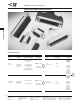
Straight Posted Connectors
HD-20 All-Plastic Straight Posted Connectors (Continued)
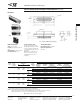
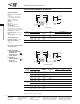
Receptacle
Material and Finish:
Housing—94V-0 rated thermoplastic,
black
Threaded Inserts—Brass, unplated
Female Screwlocks—Brass, nickel
plated
Socket Contacts (Posted)—
Phosphor bronze, plated as follows:
A—.000030 [0.00076] gold on mating
end, tin on termination end, with entire
contact .000050 [0.00127] (min.) nickel
underplated
B—Gold flash on mating end, tin on
termination end, with entire contact
.000050 [0.00127] (min.) nickel
underplated
Technical Documents:
Product Specification—108-40025
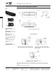
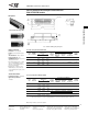
Typical Applications
Application of connector with 4-40 Threaded
Inserts using Short Female Screwlocks included
in Kit No. 207952
Application of connector with 4-40 Fixed Female
Screwlocks. (See table on next page.)
Note: Hardware parts in illustrations above are not included with the connectors listed in the table on page 85.
They are to be supplied by the Customer or, where applicable, purchased separately from TE using the part nos.
specified.
Long Female
Screwlock
(1 Kit Req'd.)
Panel
(Optional)
Pc Board
Washer
Hex Nut
Washer
Screw
Pc Board
4-40 Fixed
Female
Screwlock
Pc Board
4-40
Threaded
Insert
Panel
Short Female
Screwlock
(2 Req'd.)
Application of connector with standard mounting
holes using Long Female Screwlock Kit No. 207719
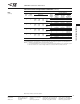
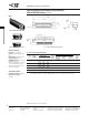
W
ith Standard Mounting Hole
With Threaded Insert
With Fixed Female Screwlock
Mating Face
.
479
±.015
[
12.17
±0.38
]
.
243
[
6.17]
.
026
[
0.66]
D
ia.
T
yp.
S
ee Table
C
M
ax.
A
Max.
+.020
D
[
-0.508]
+.015
[0.381]
±.010
B
[±0.25]
S
ee customer drawings for pcb layouts.