
Information


108-40005
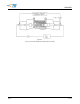
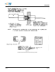
Rated Current vs Am bient Tem perature Rating For
RMS DC
Single Circuit, I or I , Maxim um W ire Gage, Continuous Operation
Figure 4A
Current Carrying Capability
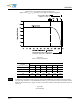
Percent
Connector Loading
W ire Size AW G
28 26 24 22 20 18
Single contact .384 .450 .536 .647 .795 1
26 .237 .278 .342 .400 .491 .618
50 .164 .193 .229 .277 .341 .428
76 .132 .155 .184 .222 .273 .344
100 .114 .134 .159 .192 .236 .297
To determine acceptable current carrying capacity per contact for percentage connector loading
NOTE
and wire gage indicated, use the Multiplication Factor (F) from the above chart and multiply it times
the Base rated Current for a single circuit at the maximum ambient operating temperature shown in
Figure 4A.
Figure 4B
Current Rating
Rev F 8 of 10