
Information

114- 10000
Rev V 7 of 11
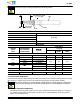
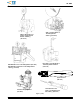
3.4. Crimped Contact Straightness
A. Twist or Roll
The crimped wire and insulation barrels must be aligned with the un--crimped portion of the contact to
within the limit shown in Figure 4.
Figure 4
Wire Barrel
Front of Contact
(Pin or Socket)
15_ (Max)
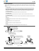
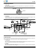
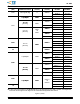
B. Straightness
Test questionable contacts using a straightness gage manufactured to the specifications of Figure 5. To be
considered acceptable for use, a contact must fully enter the gage without binding.
Figure 5
NOTES: Material Tool Steel, AISI Type 01 or 02.......
Hardness Rockwell B99 Maximum..........
Finish Black Oxide......................
1.77 + 0.03
[.0695 +
.0010] DIA
-- A --
1.07 + 0.03
[.042 +
.001] DIA
-- B --
2.16 + 0.01
[.0850 +
.0005] DIA
0.10 [.004] B
12.7 + 0.51
[.500 +
.020]
DIA
Pin End
7.11
[.280]
6.35
[.250]
7.37
[.590]
29.97 + 0.51
[1.180 +
.020]
2.16 + 0.01
[.0850 +
.0005] DIA
0.10 [.004] A
Socket
End
3.5. Solder Cup Contacts
Observe the guidelines and procedures described in Instruction Sheet 408--7799 when solder cup contacts are
required. Solder, clean, and dry all wire leads to contacts according to the following:
A. Flux Selection
Wire lead and contact wire barrel interior shall be fluxed prior to soldering using a mildly active rosin. Flux
must be compatible with manufacturing, safety, and health guidelines.
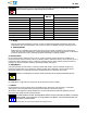
B. Cleaning
After cleaning, removal of fluxes, residues, and activators is mandatory. Cleaning procedures and solvents
depend on the type of flux used. See Figure 6.