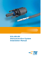
SOLARLOK Interconnection System Installation Manual
SOLARLOK Interconnection System 2-1773458-2 Issued 4-2011 Installation Manual 1. n ! n n n n n n n n Safety Note he SOLARLOK connector is to be used only to T interconnect firmly fixed cables. D o not disconnect under electrical load! E lectrical current path should only be disconnected using approved devices. Only cables released from TE Connectivity are permitted to be used with SOLARLOK component cable assemblies.
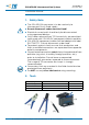
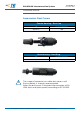
SOLARLOK Interconnection System 2-1773458-2 Issued 4-2011 Installation Manual 3. Assembly Steps 3.1 U sing the appropriate wire stripping tool, strip the wire 9 mm ± 1 mm without damaging the strands. 3.2 I nsert the stripped wire into the terminal wire crimp barrel until it stops. While holding the wire in place, squeeze the crimp tool handles together until the ratchet releases. 3.3 Press the seal and cable pinch ring assembly into the connector housing until it stops.
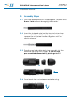
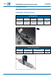
SOLARLOK Interconnection System 2-1773458-2 Issued 4-2011 Installation Manual Pre-Assembled (Connector Kit) 3.5 Push contact with cable into the connector housing until you hear the contact give an audible click and you feel the contact reach the end position. To verify contact engagement, give a slight gentle pull back on the cable, to be sure that the contact is locked. “CLICK” 3.6 Tighten the cable screw lock. The initial assembly tightening torque is 1.3 + 0.2 Nm.
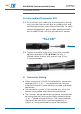
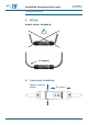
SOLARLOK Interconnection System 2-1773458-2 Issued 4-2011 Installation Manual 5. Wiring Radius (r) min. 5x cable Ø ! r = correct! 6. Connector Unmating Depress locking latches Pull apart All specifications subject to change. Consult Tyco Electronics for latest specifications. te.
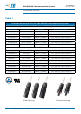
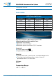
2-1773458-2 Issued 4-2011 SOLARLOK Interconnection System Installation Manual Table 1 Available Connector Kits for SOLARLOK Interconnection System Female Cable Connectors Part Number Description Wire Size 4-1394462-6 Plus Female 2.5mm / 14AWG 4.5 to 6.0 mm / 0.177-0.236 in 4-1394462-8 Plus Female 4.0mm2 / 12AWG 4.5 to 6.0 mm / 0.177-0.236 in 6-1394462-3 Plus Female 6.0mm2 / 10AWG 4.5 to 6.0 mm / 0.177-0.236 in 4-1394462-7 Minus Female 2.5mm2 / 14AWG 4.5 to 6.0 mm / 0.177-0.
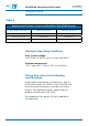
2-1773458-2 Issued 4-2011 SOLARLOK Interconnection System Installation Manual Table 2 Replacement Contacts (screw-machined) for SOLARLOK System Wire Gauge | Wire Size Male Contact PN Female Contact PN 2.5 mm | 14 AWG 0-1987280-1 0-1987281-1 4.0 mm2 | 12 AWG 0-1987280-2 0-1987281-2 6.0 mm | 10 AWG 0-1987280-4 0-1987281-3 2 2 *HVT contact system Maximum Operating Conditions Max. system voltage: 1000V (for UL 600V), max.
2-1773458-2 Issued 4-2011 SOLARLOK Interconnection System Installation Manual Accessories: Dust Covers Female Housing – Dust Cap PN Package Quantity 1987424-1 100 Male Housing – Dust Plug ! 7 PN Package Quantity 1987419-1 100 The usage of connector re-usable dust covers until final assembly is strongly recommended. When the dust cover is mounted, the connector fulfils IP44 (dust and splash proof) according to IEC 60529. All specifications subject to change.
2-1773458-2 Issued 4-2011 SOLARLOK Interconnection System Installation Manual Connector Safety Devices Locking Collar PN Unlock through Required Instruction Sheet Package Quantity 2106207-1 Flat-bladescrewdriver NEC* / USA UTE C15-712 / France 408-10296 100 *for detailed informations see NEC 2008: 690.33 Safety Clip Pivoted PN Unlock through Required Package Quantity 1534226-1 Tool less – 100 All specifications subject to change. Consult Tyco Electronics for latest specifications. te.
SOLARLOK Interconnection System 2-1773458-2 Issued 4-2011 Installation Manual Solar Cable USE-2 Solar AWG Cable Wire Size Color Part Number 14 AWG Black 1986166-2 500 Black 1986166-3 2500 Black 1986165-2 500 Black 1986165-3 1600 Black 1986164-2 500 Black 1986164-3 1000 12 AWG 10 AWG Quantity This UV resistant cable can be used in the following photovoltaic applications: n Between solar panels n Between solar roof tiles n Between panels and the AC/DC inverters Approval: UL 854 app
2-1773458-2 Issued 4-2011 SOLARLOK Interconnection System Installation Manual Grounding Solutions Grounding Clip and Grounding Bolt Only for solid un-insulated copper wire PN Description Instruction Sheet Package Quantity 1954381-1 12-10AWG Grounding Clip with Self-Tapping Screw 408-10160 100 1954381-2 12-10 AWG Grounding Clip with Screw and Nut 408-10160 100 1954381-3 12-10 AWG Grounding Clip with Screw, Nut and Locking Ring 408-10160 100 2106831-1 6-12 AWG Grounding Bolt, # 10-32 UNC Lo
FOR MORE INFORMATION te.com/solar TE Technical Support Center Internet: te.com/help USA: +1 (800) 522-6752 Canada: +1 (905) 475-6222 Mexico +52 (0) 55-1106-0800 Latin/S. America: +54 (0) 11-4733-2200 Germany: +49 (0) 6251-133-1999 UK: +44 (0) 800-267666 France: +33 (0) 1-3420-8686 Netherlands: +31 (0) 73-6246-999 China: +86 (0) 400-820-6015 Part numbers in this brochure are RoHS Compliant*, unless marked otherwise. *as defined www.te.com/leadfree te.