
Information


8
Catalog 82004 Dimensions are shown for Dimensions are in inches and Canada: +1 (905) 475-6222 UK: +44 (0) 800-267666
Revised 3-11 reference purposes only. millimeters unless otherwise Mexico/C. Am.: +52 (0) 55-1106-0800 France: +33 (0) 1-3420-8686
Specifications subject Latin/S. Am.: +54 (0) 11-4733-2200 Netherlands: +31 (0) 73-6246-999
www.te.com to change. USA: +1 (800) 522-6752
FASTON Terminals (Insulated and Uninsulated)
FASTON Terminals
Test Specifications (Continued)
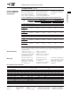
Test Parameters for FASTON Terminals (Based on UL-310 Temperature Rise and Current Requirements)
This table can be used as a guide for selecting a characteristic such as contact size, wire size, or current (either continuous or intermittent operating current)
when the other two are known. This table also identifies the possible receptacle sizes available for a given wire size. The continuous current column highlights
the maximum current that should be applied to a given receptacle and wire combination to meet a 30°C maximum temperature rise. Intermittent current can be
defined as a one hour cycle consisting of 45 minutes on and 15 minutes off. The temperature rise of the connector using the intermittent current on the
corresponding wire size will be less than 85° C. The wire used in the testing to meet these electrical requirements is tin plated copper with stranding as
indicated above in parentheses for terminals intended for internal wiring connections.
Wire Size (Strand Count)
10 (105)
12 (65)
14 (41)
16 (26)
18 (16)
20 (10)
22 (7)
16 (26)
18 (16)
20 (10)
22 (7)
Continuous Current
24
20
15
10
7
4
3
5
4
3
2
Intermittent Current
48
40
30
20
14
8
6
10
8
6
4
Contact Size
250
Series
205
Series
187
Series
110
Series
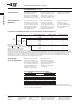
The forces shown for the crimp pull out test represent the minimum force required to separate the wire from the
crimped terminal in an axis parallel to the wire exit direction from the contact. This force does not include the holding
force of the insulation crimp (if applicable).
Forces for Crimp Pull-out Test (UL-310 Specification)
Wire Size Minimum Force
AWG (mm
2
) pounds N
22 0.32 8 36
20 0.52 13 58
18 0.82 20 89
16 1.3 30 133
14 2.1 50 223
12 3.3 70 311
10 5.3 80 356
Note: This information applies only to
UL listed terminals. A part with a
component recognition status deviates
from the electrical or other requirements
defined in the UL-310 safety standard.
R
R
Test Specifications
The following information
and related charts are
taken from the qualification
requirements as defined in
UL-310, the safety standard
for electrical Quick-Connect
terminals. Throughout this
catalog, when a reference
is made to a part being UL
listed, that part has been
qualified to the standards
shown in these charts.
Temperature Rise and
Millivolt Drop
The temperature rise and
millivolt drop characteristics
are the lowest in the indus-
try. They comply with safety
requirements and exhibit
extreme stability during
extended time tests.
When using FASTON
terminals, the allowable
connection temperatures
can be adjusted, based on
the application, by consid-
ering actual current(s) and
related temperature rise,
time at this temperature,
humidity, corrosion
environment, vibration,
base metal, plating (if any),
and other environmental
considerations.
Tensile Strength
(forces for crimp pull-out)
Maximum tensile strength
of the wire to terminal con-
nection does not insure reli-
able electrical performance.
An acceptable compromise
between maximum tensile
strength and electrical
stability is recommended.
Normally the tensile
strength is much greater
than the force required to
disconnect the tab from the
receptacle; therefore, no
difficulties or hazards are
encountered.
specified.
Germany: +49 (0) 6251-133-1999 China: +86 (0) 400-820-6015