
User Manual


114- 13120
Rev E 13 of 17
C
A
G
E
A
S
S
E
M
B
L
Y
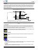
DIMENSION (Non--PCI Application)
CAGE ASSEMBL
Y
C
O
N
F
I
G
U
R
A
T
I
O
N
SFP+ CAGE ASSEMBLY With External EMI Panel Gr ound Springs
C
O
N
F
I
G
U
R
A
T
I
O
N
A+0.1 B(Min) C+0.1 D+0.1 E
Single Port 15.25 16.25 10.4 0.23 3.5+0.3
1¢2 Ganged 29.70 30.75 10.4 0.23 3.5+0.3
1¢4 Ganged 58.20 59.25 10.4 0.23 3.5+0.3
1¢6 Ganged 86.70 87.75 10.4 0.23 3.5+0.3
Note: Not to Scale
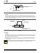
PCI
A
p
p
l
i
c
a
t
i
o
n
AA
BB
CC
Cutout Centerline to Cutout Centerline
Cutout in Bezel
Y
Y
Section Y--Y
EE (Distance Between
Back of PC Board
Cutout and Bezel)
DD
(Top of PC Board
to Bottom of
Cutout in Bezel)
PC Board
PC Board
10.8 (Ref)
0.30 Maximum Radius
(4 Places Each Cutout)
Cutout in PC Board
FF (Distance Between
Front of PC Board Cutout
and Bezel)
C
A
G
E
A
S
S
E
M
B
L
Y
DIMENSION (PCI Application)
CAGE ASSEMBL
Y
C
O
N
F
I
G
U
R
A
T
I
O
N
SFP and SFP+ CA GE ASSEMBLY
C
O
N
F
I
G
U
R
A
T
I
O
N
AA +0.1 BB (Min) CC +0.1 DD +0.1 EE FF
Single Port 15.25 16.25 10.40 0.40 3.5+0.3 1.02+0.3
1x6 Ganged 86.5 87.75 10.15 0.65 3.5 +0.3 1.02 +0.3
Figure 10 (End)
3.17. Cage Assembly Placement
The connector must be soldered to the pc board BEFORE seating the cage assembly.
A. Registration
The compliant pin contacts and EMI suppression pins must be aligned with matching holes in the pc
board, then inserted into the pc board simultaneously to prevent twisting or bending of these parts.
B. Seating
Using proper seating force and seating height is essential to interconnection performance. The force used
to seat the cage assembly must be applied evenly to prevent deformation or other damage to the
compliant pin contacts. The force required to seat the cage assembly onto the pc board can be calculated
by:
Amount of Compliant Pin Contacts ¢ 44.5 N [10 lbs] (Force per Compliant Pin Contact) = Seating Force
Over--driving of the cage assembly will deform parts critical to the quality of the connection. Maximum force occurs
prior to the cage assembly bottoming on the pc board.
NOTE
i
CAUTION
!