
User Manual


114- 13120
Rev E14 of 17
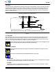
When using tooling to seat a ganged cage assembly, the shut height of the application tool must be
specifically set for proper seating of the cage assembly. The shut height can be calculated by:
Seating Height (Cage Assembly Seated) + Height of Seating Tool + Combined Thicknesses of
PC Board and PC Board Support Fixture = Shut Height (Ram Down)
The shut height may need to be adjusted to maintain the 0.10 mm maximum gap between the standoffs of the cage
assembly and the pc boar d.
The cage assembly must be seated on the pc board not exceeding the dimensions shown in Figure 11.
0.10 (Max) Gap
Cage Assembly Standoffs
to PC Board
Cage Assembly
9.70 (Ref)
Seating Height (Top of Cage Assembly—
Not Including Panel Grounding Feature—to PC Board)
PC Board
Compliant Pin
Contacts
EMI Suppression
Pins
Note: Single Port Cage Assembly Shown—Requirements Also Apply to Ganged Cage Assemblies
Requirements Do Not Apply to Cage Assemblies with Light Pipe
Figure 11
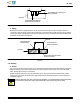
3.18. Checking Installed Cage Assembly
After installation, the cage assembly panel grounding feature must be compressed by the bezel. A slight bow in
the cage assembly is permitted. The bezel must not interfere with the function of the module locking latch. The
bezel and pc board must be positioned according to the dimensions shown in Figure 12.
3.19. Port Protection
A dust cover (for SFP cage assembly) or EMI plug assembly (for SFP+ cage assembly) must be installed into
the port when the transceiver module is not mated with the cage assembly.
3.20. Removal and Repair
The cage assembly must be removed from the pc board before removing the connector. Standard
de--soldering methods must be used to remove the connector from the pc board. The connector and cage
assembly MUST NOT be re--used after removal.
For removal of the single port cage assembly, a flat metal bar (or similar object) can be partially inserted into
the port of the cage assembly (the object MUST NOT touch the connector; otherwise, damage to the surface
mount contacts could occur), then the cage assembly can be removed by lifting it off of the pc board.
For removal of a ganged cage assembly, an extraction tool must be used (refer to Section 5).
The connector and cage assembly are not repairable. Any defective or damaged products MUST NOT be
used.
4. QUALIFICATION
SFP and SFP+ surface mount PT connectors are Recognized by Underwriters Laboratories Inc. (UL) in File
E28476.
NOTE
i