
User Manual


114- 13120
Rev E 17 of 17
6. VISUAL AID
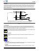
Figure 14 shows a typical application of SFP and SFP+ surface mount PT connectors and cage assemblies.
This illustration should be used by production personnel to ensure a correctly applied product. Applications
which DO NOT appear correct should be inspected using the information in the preceding pages of this
specification and in the instructional material shipped with the product or tooling.
FIGURE 14. VISUAL AID
Note: Single Port Cage Assembly Shown
Requirements Also Apply to Ganged Cage Assembly
Requirements Do Not Apply to Cage Assembly with Light Pipe
CONTACT SOLDER TINES MUST
BE SEATED ON CIRCUIT PADS
SOLDER FILLET MUST BE
FORMED EVENLY AROUND
EACH CONTACT SOLDER TINE
STANDOFFS MUST BE
SEATEDONPCBOARD
CONTACT SOLDER TINE
MUST BE CENTERED ON
CIRCUIT PADS (Slight
Misalignment is Allowed)
SLIGHT BOW IN CAGE
ASSEMBLY PERMITTED
CAGE ASSEMBLY PANEL
GROUNDING FEATURE MUST
BE COMPRESSED BY BEZEL
BEZEL MUST NOT INTERFERE WITH
FUNCTION OF CAGE ASSEMBLY
MODULE LOCKING LATCH
ALL COMPLIANT PIN CONTACTS
AND EMI SUPPRESSION PINS
MUST BE FULLY INSERTED INTO
MATCHING PC BOARD HOLES
CAGE ASSEMBLY MUST NOT
BE DAMAGED IN ANY WAY
DUST COVER (SFP Cage Assembly) OR EMI PLUG
ASSEMBLY (SFP+ Cage Assembly) (Not Shown)
MUST BE IN STALLED IN PORT WHEN TRANSCEIVER
MODULE IS NOT MATED WITH CAGE ASSEMBLY
CONNECTOR MUST NOT BE
DAMAGED IN ANY WAY
ALIGNMENT POSTS MUST BE
FULLY INSERTED INTO M ATCHING
PC BOARD HOLES