
User Manual


114- 13120
Rev E 3 of 17
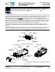
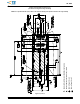
Each connector is a housing with right--angle surface mount contacts. The connector features an embossed “1”
for Pin 1 identification, a chamfered corner for orientation, alignment posts that provide stability for placement
on the pc board, standoffs to allow easy pc board cleaning after soldering, and a card entry slot that accepts a
1.0+
0.1 mm thick integrated circuit card housed in the transceiver module.
Each cage assembly is a frame with compliant pin contacts; available with or without electromagnetic
interference (EMI) suppression pins. The cage assembly features thermal vent holes, a locking latch for
holding the mating transceiver module in place, kick--out spring to release the transceiver module for removal,
and panel grounding features (panel ground springs and elastomeric gasket) to provide electrical contact to the
bezel. The dust cover (SFP cage assemblies) or the EMI plug assembly (SFP+ cage assemblies)—one for
each port—is used when the transceiver module is not mated to the cage assembly to prevent contaminants
from entering the chassis.
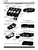
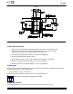
The SFP+ cage assembly is available in two versions: elastomeric gasket, and external EMI panel ground
springs (springs are on the outside of the cage assembly). The elastomeric gasket cage assembly is available
in ganged only. The external EMI panel ground springs cage assembly is available in single port and ganged
(1¢2, 1¢4, and 1¢6). Both versions are available with or without light pipes.
2. REFERENCE MATERIAL
2.1. Revision Summary
Revisions to this application specification include:
S Updated document to corporate requirements
S New logo
2.2. Customer Assistance
Reference product base part numbers 1367073 and 1489669 and product code A438 are representative of
SFP surface mount PT connectors and cage assemblies, and reference product base part numbers 1888247
and 2007135 and product code K638 are representative of SFP+ surface mount PT connectors and cage
assemblies. Use of these numbers will identify the product line and expedite your inquiries through a service
network established to help you obtain product and tooling information. Such information can be obtained
through a local Representative or, after purchase, by calling PRODUCT INFORMATION at the number at the
bottom of page 1.
2.3. Drawings
Customer drawings for product part numbers are available from the service network. If there is a conflict
between the information contained in the customer drawings and this specification or with any other technical
documentation supplied, the information contained in the customer drawings takes priority.
2.4. Specifications
Product Specifications 108--1949 (SFP connector) and 108--1950 (SFP cage assemblies) provides product
performance and test information.
2.5. Instructional Material
Instruction Sheets (408--series) provide product assembly instructions or tooling setup and operation
procedures. Documents available which pertain to this product are:
408--8848 SFP PT Connector and Cage Assembly Seating Tool Kit
408--8849 SFP Cage Assembly Extraction Tool
408--10300 SFP+ Cage Assembly Removal Tool Assemblies 1976584--1, 1976597--1, and 1976920--1
3. REQUIREMENTS
3.1. Safety
Do not stack component packages so high that the shipping containers buckle or deform.
3.2. Limitations
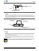
A. Connector
The connector is designed to operate in a temperature range of --55_ to 85_C[--67_ to 185_F].