
User Manual


114- 13120
Rev E4 of 17
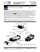
B. Transceiver Module
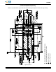
For applications using ganged cage assemblies, the width of the mating transceiver module (portion
outside of the cage assembly) cannot exceed the width of the port of the cage assembly. This will prevent
any possible interference between ports when inserting the transceiver modules. Port--to--port centerline
spacing is 14.25 mm; therefore, the maximum width of the transceiver (outside of the cage assembly)
cannot exceed 14 mm.
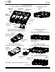
3.3. Material
The connector housing is made of liquid crystal polymer (LCP) thermoplastic, UL 94--V--0. The surface mount
contacts are made of phosphor bronze plated with gold over nickel. The cage assemblies are made of copper
alloy. The dust cover is made of thermoplastic, and the EMI plug assembly is made of zinc die cast with a
copper alloy spring.
3.4. Storage
A. Ultraviolet Light
Prolonged exposure to ultraviolet light may deteriorate the chemical composition used in the connector
material.
B. Shelf Life
The connector and cage assembly should remain in the shipping containers until ready for use to prevent
deformation to any protruding parts. The connectors and cage assemblies should be used on a first in, first
out basis to avoid storage contamination that could adversely affect performance.
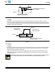
C. Reeled Components
The connectors are supplied in reels on carrier tapes approved under Electronic Industries Alliance
(EIA)--481. These reels have a maximum diameter of 360 with 480 connectors per reel. Store coil wound
reels horizontally and traverse wound reels vertically.
Refer to Section 5 for carrier tape dimensions.
3.5. Chemical Exposur e
Do not store connectors or cage assemblies near any chemical listed below as they may cause stress
corrosion cracking in the contacts.
Alkalies Ammonia Citrates Phosphates Citrates Sulfur Compounds
Amines Carbonates Nitrites Sulfur Nitrites Tartrates
3.6. PC Board
A. Material and Thickness
The pc board material shall be glass epoxy (FR--4 or G--10). The minimum pc board thickness must be
1.5 mm for mounting the connector and cage assembly to one side of the board. For mounting to both
sides of the board, the minimum pc board thickness must be 3.0 mm for single port cage assemblies and
2.25 mm for SFP ganged, SFP enhanced EMI ganged, and SFP+ external EMI panel ground spring cage
assemblies.
B. Tolerance
Maximum allowable bow of the pc board shall be 0.08 mm over the length of the cage assembly. The
coplanarity of the pc board circuit pads must be 0.03 mm.
C. Pads
The pads must be solderable in accordance with EIA--364--52.
D. Hole Dimension
The holes for the cage assembly compliant pin contacts must be drilled and plated through.
Recommended drilled hole diameter and plating type and thickness, and reference finished hole size are
provided in Figure 2.
NOTE
i