
User Manual


114- 13120
Rev E6 of 17
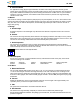
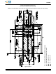
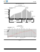
Figure 3 (Cont’d)
Sampl e Recomm ended PC Board Layout
(Connector and Single Port Cage Assem bly)
Note: For a Specific PC Board Layout, Refer to the Customer Drawing for the Specific Connector and Cage Assembly
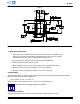
Refer to Figure 2, Hole A
RefertoFigure2,HoleC
Datum and Basic Dimension Established by Customer
Pads and Vias and Chassis Ground, 11 Places