
User Manual


114- 13120
Rev E 9 of 17
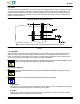
PC Board
Contact Solder Tine Centered on
PC Board Circu it Pad Preferred
Contact Solder Tine Overhang Up to
50% is Permissible
Figure 5
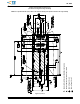
C. Seating
Because the connector alignment posts are for clearance and fit only, the force required to seat the
connector is minimal. Apply only that force necessary to seat the contact solder tines into the top surface
of the solder paste. The alignment posts must be inserted into the pc board holes and the standoffs must
be seated on the board. See Figure 6.
Figure 6
PC Board
Connector
Alignment Post (2 Places) Inserted
into Hole in PC Board
Contact Solder Tine
Seated on Circuit Pad
Standoff (2 Places)
Seated on Board
3.13. Soldering
A. Process
The connector must be soldered using non--focused infrared (IR) reflow or equivalent soldering technique.
When mounting to both sides of the pc board, the surface tension of the solder, when it is in the liquid
state, will hold the connector on the board.
Reflow temperature and time may vary depending on the size of the pc board and placement of other
components. The reflow temperature and approximate time to which the connector can be subjected is
specified in Figure 7.
Excessive temperatures may cause connector housing degr adation. It is recommended that component temperatures
not exceed 230_C [446_F] when using tin--lead solder and 260_C [500_F] when using lead--free solder .
CAUTION
!