
Datasheet

01-2016, Rev. 0116
www.te.com
© 2015 Tyco Electronics Corporation,
a TE Connectivity Ltd. company
Datasheets and product specification
according to IEC 61810-1 and to be used
only together with the ‘Definitions’ section.
Datasheets and product data is subject to the
terms of the disclaimer and all chapters of
the ‘Definitions’ section, available at
http://relays.te.com/definitions
Datasheets, product data, ‘Definitions’ sec-
tion, application notes and all specifications
are subject to change.
2
AXICOM
Signal Relays
IM - E Relay (Continued)
Other Data
Material compliance: EU RoHS/ELV, China RoHS, REACH, Halogen content
refer to the Product Compliance Support Center at
www.te.com/customersupport/rohssupportcenter
Ambient temperature -40°C to +85°C
Thermal resistance <150K/W
Category of environmental protection
IEC 61810 RT V - hermetically sealed
Degree of protection
IEC 60529 IP 67, immersion cleanable
Vibration resistance (functional) 20g, 10 to 500Hz
Shock resistance (functional), half sinus 11ms, 50g
Shock resistance (destructive), half sinus 0.5ms 500g
Weight max. 0.75g
Resistance to soldering heat THT Peek value
IEC 60068-2-20 265°C/10s
Resistance to soldering heat SMT
IEC 60068-2-58 265°C. / 10s
Moisture sensitive level, JEDEC J-Std-020D MSL3
related only to SMT relays
packed in orginal dry-packs
Washing see application notes
Ultrasonic cleaning not recommended
Storage conditions 3 years
Packaging/unit
THT version tube/50 pcs, box/1000 pcs
SMT version
reel/1000 pcs., box/1000 or 5000 pcs.
Insulation*
Initial dielectric strength
between open contacts 1000V
rms
between contact and coil 1800V
rms
between adjacent contacts 1000V
rms
Initial surge withstand voltage
between open contacts 1500V
between contact and coil 2500V
between adjacent contacts 1500V
Initial insulation resistance
between insulated elements >10
9
Ω
Capacitance
between open contacts max. 1pF
between contact and coil max. 2pF
between adjacent contacts max. 2pF
*this relay contains SF6 (Sulfur hexafluoride, CAS number: 2551-62-4) for dielectric strength
enhancement, SF6 is hermetically sealed in relay without leaks to air during normal applica-
tion as recommended per the applicable product specification. It is clarified that the usage
of SF6 in mini signal relay is not prohibited by related regulations. Please contact TE local
sales or field engineer for further information and detailed material declaration.
RF Data
Isolation at 100MHz/900MHz 37.0dB / 18.8dB
Insertion loss at 100MHz/900MHz 0.03dB / 0.33dB
Voltage standing wave ratio (VSWR)
at 100MHz/900MHz 1.06 / 1.49
THT version
Dimensions
108-98001 Rev. M
All specifications subject to change. Consult Tyco Electronics for latest specifications. 16 of 28
AXICOMÊSignalÊRelays
IM-D Relay 2 Pole Break / 2 Form B / DPST NC
IMÊTHT
Standard
IMÊSMT
GullÊWings
mm inch mm inch
L
W
H
10.00ʱÊ0.08
6.00ʱÊ0.08
5.65ÊÐÊ0.20
0.393ʱÊ0.003
0.236ʱÊ0.003
0.222ÊÐÊ0.008
10.00ʱÊ0.08
ÊÊ6.00ʱÊ0.08
ÊÊ5.65ÊÐÊ0.20
0.393ʱÊ0.003
0.236ʱÊ0.003
0.222ÊÐÊ0.008
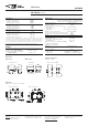
THT Version
Standard Version
SMT Version
Mounting Hole Layout
View onto the component side of the PCB (top view)
Solder Pad Layout
View onto the component side of the PCB (top view)
Dimensions IM-D
Dimensions in mm
Terminal Assignment
Relay – top view
Non-Latching Type
not energized condition
Latching Type, 1 Coil
reset condition
Coplanarity ≤ 0.1mm
Gull Wings
T
T1
T2
D1
D2
Tw
S
3.2
N/A
5.08ʱÊ0.10
3.20ʱÊ0.15
2.20ʱÊ0.15
0.40
0.75
0.125
N/A
0.200ʱÊ0.004
0.126ʱÊ0.006
0.087ʱÊ0.006
0.015
0.029
N/A
7.50ʱÊ0.30
5.08ʱÊ0.10
3.20ʱÊ0.15
2.20ʱÊ0.15
0.4
N/A
N/A
0.295ʱÊ0.011
0.200ʱÊ0.004
0.126ʱÊ0.006
0.087ʱÊ0.006
0.015
N/A
10.0±0.08
6.0±0.08
7.5±0.3
5.08±0.1
5.4
0.4
5.65-0.2
Coplanarity ≤0.1mm
10.0±0.08
6.0±0.08
0.4
5.65-0.2
5.08±0.1
5.4 2.2
0.75
3.2
2.2
SMT version
108-98001 Rev. M
All specifications subject to change. Consult Tyco Electronics for latest specifications. 16 of 28
AXICOMÊSignalÊRelays
IM-D Relay 2 Pole Break / 2 Form B / DPST NC
IMÊTHT
Standard
IMÊSMT
GullÊWings
mm inch mm inch
L
W
H
10.00ʱÊ0.08
6.00ʱÊ0.08
5.65ÊÐÊ0.20
0.393ʱÊ0.003
0.236ʱÊ0.003
0.222ÊÐÊ0.008
10.00ʱÊ0.08
ÊÊ6.00ʱÊ0.08
ÊÊ5.65ÊÐÊ0.20
0.393ʱÊ0.003
0.236ʱÊ0.003
0.222ÊÐÊ0.008
THT Version
Standard Version
SMT Version
Mounting Hole Layout
View onto the component side of the PCB (top view)
Solder Pad Layout
View onto the component side of the PCB (top view)
Dimensions IM-D Dimensions in mm
Terminal Assignment
Relay – top view
Non-Latching Type
not energized condition
Latching Type, 1 Coil
reset condition
Coplanarity ≤ 0.1mm
Gull Wings
T
T1
T2
D1
D2
Tw
S
3.2
N/A
5.08ʱÊ0.10
3.20ʱÊ0.15
2.20ʱÊ0.15
0.40
0.75
0.125
N/A
0.200ʱÊ0.004
0.126ʱÊ0.006
0.087ʱÊ0.006
0.015
0.029
N/A
7.50ʱÊ0.30
5.08ʱÊ0.10
3.20ʱÊ0.15
2.20ʱÊ0.15
0.4
N/A
N/A
0.295ʱÊ0.011
0.200ʱÊ0.004
0.126ʱÊ0.006
0.087ʱÊ0.006
0.015
N/A
10.0±0.08
6.0±0.08
7.5±0.3
5.08±0.1
5.4
0.4
5.65-0.2
Coplanarity ≤0.1mm
10.0±0.08
6.0±0.08
0.4
5.65-0.2
5.08±0.1
5.4 2.2
0.75
3.2
2.2
Standard version Gull wings
Terminal assignment
TOP view on relay
108-98001 Rev. M
All specifications subject to change. Consult Tyco Electronics for latest specifications. 18 of 28
AXICOMÊSignalÊRelays
IM-E Relay 2 Pole Make / 2 Form A / DPST NO
IMÊTHT
Standard
IMÊSMT
GullÊWings
mm inch mm inch
L
W
H
10.00ʱÊ0.08
6.00ʱÊ0.08
5.65ÊÐÊ0.20
0.393ʱÊ0.003
0.236ʱÊ0.003
0.222ÊÐÊ0.008
10.00ʱÊ0.08
ÊÊ6.00ʱÊ0.08
ÊÊ5.65ÊÐÊ0.20
0.393ʱÊ0.003
0.236ʱÊ0.003
0.222ÊÐÊ0.008
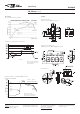
THT Version
Standard Version
SMT Version
Gull Wings
Mounting Hole Layout
View onto the component side of the PCB (top view)
Solder Pad Layout
View onto the component side of the PCB (top view)
Dimensions IM-E Dimensions in mm
Terminal Assignment
Relay – top view
Non-Latching Type
not energized condition
Latching Type, 1 Coil
reset condition
Coplanarity ≤ 0.1mm
T
T1
T2
D1
D2
Tw
S
3.2
N/A
5.08ʱÊ0.10
3.20ʱÊ0.15
2.20ʱÊ0.15
0.40
0.75
0.125
N/A
0.200ʱÊ0.004
0.126ʱÊ0.006
0.087ʱÊ0.006
0.015
0.029
N/A
7.50ʱÊ0.30
5.08ʱÊ0.10
3.20ʱÊ0.15
2.20ʱÊ0.15
0.4
N/A
N/A
0.295ʱÊ0.011
0.200ʱÊ0.004
0.126ʱÊ0.006
0.087ʱÊ0.006
0.015
N/A
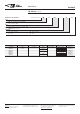
IM-E, 2 form A (2 NO)
PCB layout
TOP view on component side of PCB
THT mounting holes SMT - solder pads
108-98001 Rev. M
All specifications subject to change. Consult Tyco Electronics for latest specifications. 16 of 28
AXICOMÊSignalÊRelays
IM-D Relay 2 Pole Break / 2 Form B / DPST NC
IMÊTHT
Standard
IMÊSMT
GullÊWings
mm inch mm inch
L
W
H
10.00ʱÊ0.08
6.00ʱÊ0.08
5.65ÊÐÊ0.20
0.393ʱÊ0.003
0.236ʱÊ0.003
0.222ÊÐÊ0.008
10.00ʱÊ0.08
ÊÊ6.00ʱÊ0.08
ÊÊ5.65ÊÐÊ0.20
0.393ʱÊ0.003
0.236ʱÊ0.003
0.222ÊÐÊ0.008
THT Version
Standard Version
SMT Version
Mounting Hole Layout
View onto the component side of the PCB (top view)
Solder Pad Layout
View onto the component side of the PCB (top view)
Dimensions IM-D Dimensions in mm
Terminal Assignment
Relay – top view
Non-Latching Type
not energized condition
Latching Type, 1 Coil
reset condition
Coplanarity ≤ 0.1mm
Gull Wings
T
T1
T2
D1
D2
Tw
S
3.2
N/A
5.08ʱÊ0.10
3.20ʱÊ0.15
2.20ʱÊ0.15
0.40
0.75
0.125
N/A
0.200ʱÊ0.004
0.126ʱÊ0.006
0.087ʱÊ0.006
0.015
0.029
N/A
7.50ʱÊ0.30
5.08ʱÊ0.10
3.20ʱÊ0.15
2.20ʱÊ0.15
0.4
N/A
N/A
0.295ʱÊ0.011
0.200ʱÊ0.004
0.126ʱÊ0.006
0.087ʱÊ0.006
0.015
N/A
10.0±0.08
6.0±0.08
7.5±0.3
5.08±0.1
5.4
0.4
5.65-0.2
Coplanarity ≤0.1mm
10.0±0.08
6.0±0.08
0.4
5.65-0.2
5.08±0.1
5.4 2.2
0.75
3.2
2.2