
Datasheet

408-9833
2 of 3
Rev D
Dimensions in these instructions are in metric units
[with U.S. customary units in brackets], unless
otherwise indicated.
Reasons for reissue are provided in Section 6,
REVISION SUMMARY.
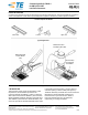
2. DESCRIPTION (Figure 1)
The connector-specific kit features an upper tool, two
locators, and a lower insert. The upper tool applies an
even force over the length of the connector during
termination. The locators and the lower insert position
the connector on the tooling assembly. Each
component is marked "AMP HDF."
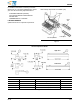
3. CABLE REQUIREMENTS
The connector-specific kit will terminate ribbon cable
with 26 AWG solid or stranded conductors, and 28
AWG solid or stranded conductors to all AMP-LATCH
HDF Low-Profile Connectors. Refer to Figure 2 for the
recommended cable dimensions.
Figure 2
The cable must be cut 90º to the edge of the cable;
otherwise an improper termination will result. We
suggest you use a guillotine-type cable cutter, such
as the Carpenter Model 95 which can be
purchased from:
Carpenter Manufacturing Co., Inc.
Fairgrounds Drive
Manlius, N.Y. 13207
Figure 3
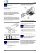
4. CONNECTOR-SPECIFIC KIT INSTALLATION
(Figure 3 and Figure 4)
For hand tool applications, mount the hand tool
onto a suitable work surface, whenever possible,
before terminating the connectors. Refer to the
bench-clamping instructions in 408-9828,
packaged with the AMP-LATCH Hand Tool Kit.
1. Slide the upper tool onto the upper tool mount.
2. Slide the lower insert into the slot of the fluted
plate.
3. Install the locators into base of tool, as shown in
Figure 4.
This completes the installation procedure.
For information concerning termination procedures,
refer to 408-9828 packaged with the AMP-LATCH
Hand Tool Kit, and 408-9827 packaged with the
Base Assembly Universal Arbor Tool.
5. CONNECTOR-SPECIFIC KIT INSPECTION
Connector-Specific Kit 768349-1 has been inspected
and should be verified with the information provided in
Figure 5. It is recommended that the connector-
specific kit be inspected immediately upon its arrival at
your facility (and at regularly scheduled intervals) to
ensure that the kit components have not been
damaged during handling.
CONDUCTOR DIMENSION
SIZE
(AWG)
TYPE “A” “B”
26 - 28
Solid or
Stranded
0.94
[.037]
1.27 [.050] X (Total No. of
Conductors Minus One)
NOTE
i
“B” + (See Note)
.635 ± .178
[.025 ± .007] (Typ)
1.27 ± .076
[.050 ± .003]
“A”± 0.13 [.005]
NOTE
i
AMP-LATCH Hand Tool Kit 768340-1 (Ref) (Includes
AMP-LATCH Hand Tool Subassembly 768942-1 and
Base Assembly Universal Hand Tool 768339-1.)
Locators
Upper Tool
Lower Insert
Slot of
Fluted
Plate
Refer to Instruction Sheet 408-9846 and 408-9826.
NOTE
i
NOTE
i