
Datasheet

LIGHT-N-LOK Connectors
114-13204
Rev
B2
of 7
Tyco Electronics Corporation
3. REQUIREMENTS
3.1. Storage
A. Ultraviolet Light
Prolonged exposure to ultraviolet light may deteriorate the chemical composition used in the connector
housing material.
B. Shelf Life
The connectors should remain in the shipping containers until ready for use. The connectors should be
used on a first in, first out basis.
3.2. Material
The housings are made of polyamide and the contacts are made from tin–plated copper alloy.
3.3. Wire Selection and Preparation
A. Type
The wire size for these connectors is 18 AWG solid, soft annealed copper wire, tinned or untinned.
B. Preparation
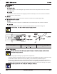
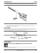
Insulation strip length, as well as the maximum insulation diameter are provided in Figure 2.
Do not nick, scrape, or cut the wire conductor during the stripping operation.
Insulation
Diameter
Strip Length
Insulation
Conductor
Strip
Gage
Plug Connector
WIRE SIZE (AWG) STRIP LENGTH INSULATION DIAMETER (MAX)
18 9.53 +0.80 [.375 +.031] 2.18 [.086]
Figure 2
3.4. Assembly Procedure
In the field, these kits must be assembled by a qualified electrician in accordance with national and local electrical
codes and the following instructions.
1. Select the proper assembly for your production requirements.
2. If using customer assembled connectors, strip two wires with 18 AWG solid copper conductors having
a maximum insulation diameter of 2.18 mm [.086 in.] to the dimensions provided in Figure 2.
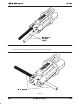
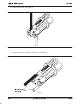
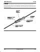
3. Insert each stripped wire into an insertion hole in the back of the plug or receptacle until bottomed.
For field wiring, black and white wires must be inserted into corresponding holes marked “B” or “W”. The
“B” (Black) wire insertion hole is also indicated by a black mark on the side of the housing. See Figure 3.
Pull back gently on the wires to ensure they have latched fully in the housings.
CAUTION
!
CAUTION
!
NOTE
i