
User Manual


AMP Metrimate
Pin and Socket Connectors
10
Catalog 82045 Dimensions are in millimeters Dimensions are shown for USA: 1-800-522-6752 South America: 55-11-3611-1514
Revised 06-08 and inches unless otherwise reference purposes only. Canada: 1-905-470-4425 Hong Kong: 852-2735-1628
specified. Values in brackets are Specifications subject Mexico: 01-800-733-8926 Japan: 81-44-844-8013
www.tycoelectronics.com equivalent U.S. Customary Units. to change. C. America: 52-55-5-729-0425 UK: 44-141-810-8967
NOTE: All part numbers
are RoHS Compliant
Signal Contacts (Continued)
Wire Size
Contact
Loose Piece
Range
Finish
Contact No.
AWGmm
2
Pin Socket
26-200.12-0.6 Gold/Nickel
1
266182-1 266183-1
18-16 0.8-1.4Gold/Nickel
1
266180-1 266181-1
Solder Tab
4
Duplex
2
202236-7 202237-7
Bright Tin 202236-5 202237-5
1
.000030 [0.00076] gold in mating area over .000030 [0.00076] min. nickel.
2
Duplex plated .000030 [0.00076] gold in mating area over .000030 [0.00076] min. nickel on contact body; bright tin on
solder tab.
3
Bright tin on entire contact.
4
Designed for up to 14 AWG; but, not to exceed current limitation of contact.
Note: These contacts can be used in Multimate contact cavities of all connector housings.
‡Single contact, free-air test current is not to be construed as contact rating current. Use only for testing.
Refer to contact current carrying capability information on page 8.
Extraction Tool Part No. 305183
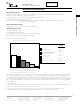
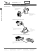
Contact Size 16—Pin Diameter .062 [1.57] (Test Current, 13 Ampere)‡
Pin Socket
Solder-Tab
Solder-Type
(with Preformed Wire Barrel/
Insulation Support)
Type III+ (Precision
Formed, Solder)
Contact Size - 16
Pin Diameter - .062 [1.57]
Material and Finish
Contact Body - Copper alloy,
plated tin to gold
Spring - Stainless steel
Related Product Data
Performance Characteristics -
Page 6
Technical Documents -
Page 80
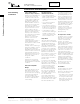
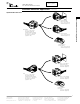
Contacts
Type III+, Crimp, Snap-In
Contact Size - 16
Pin Diameter - 1.57 [.062]
Material and Finish
Contact Body - Copper alloy,
plated tin or gold
Spring - Stainless steel
Grounding Pin
(make first - break last)
Related Product Data
Application Tooling -
Pages 56, 57
Technical Documents -
Page 58
Wire Size Range
Ins.
Grounding Pin Part No.
Strip Form Loose Piece
Dia.
Contact
Applicator Hand Tool
[mm
2
] AWG
Range
1
Finish
Strip Form
Loose Piece
Part No. Part No.
0.89-1.4
Tin 164159-3 164162-1
—
91515-1
3
or
0.12-0.2 26-24
.035-.055
Sel. Gold/Nickel
2
164159-4 164162-2
58495-1*
1.14-1.78
Bright Tin 164160-3 164163-1
466323-
***
91515-1
3
or
0.2-0.6 24-20
.045-.070
or
91505-1
3
or
Sel. Gold/Nickel
2
164160-4 164163-2
466907-2*** 58495-1*
1.98-2.49
Tin 164161-3 164164-1 466741-
*** 91523-1
3
or
0.8-1.4 18-16
.078-.098
or 91505-1
3
or
Sel. Gold/Nickel
2
164161-4 164164-2
680114-3*** 58495-1*
1
Overall insulation crimp diameter, including crimp barrel, must not exceed 3.18 [.125].
2
Gold flash over 0.00076 [.000030] min. nickel on entire contact, with 0.00076 [.000030] gold in contact area.
3
To use with the 626 Pneumatic Tool System: remove the crimping head from the Straight Action Hand Tool (SAHT) Assembly, order SAHT Adapter
Part No. (Call Technical Support), Adapter Holder Part No. 356304-1 (with ratchet) or 189928-1 (without), and Power Unit Part No. 189721-1
(hand actuated) or 189722-1 (foot actuated).
*Commercial PRO-CRIMPER II hand tool for field repair only. Note: Die Set can be adapted for use with the 626 Pneumatic Tool System.
***Call Technical Support for Automatic Machine Applicator Part Numbers.
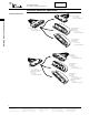
Extraction Tool Part No. 725840-1
Pin
Socket