
User Manual

5
AMP Metrimate
Pin and Socket Connectors
Catalog 82045 Dimensions are in millimeters Dimensions are shown for USA: 1-800-522-6752 South America: 55-11-3611-1514
Revised 06-08 and inches unless otherwise reference purposes only. Canada: 1-905-470-4425 Hong Kong: 852-2735-1628
specified. Values in brackets are Specifications subject Mexico: 01-800-733-8926 Japan: 81-44-844-8013
www.tycoelectronics.com equivalent U.S. Customary Units. to change. C. America: 52-55-5-729-0425 UK: 44-141-810-8967
NOTE: All part numbers
are RoHS Compliant
contact. The curve is usu-
ally flat up to 75°C ambient
and then drops off. Up to
75°C, the 30°C T-rise limits
the amount of current, and
above 75°C the current
must be reduced to keep
the combination of ambi-
ent temperature and T-rise
from exceeding the maxi-
mum operating tempera-
ture of 105°C.
Next are rating factors, a •
table of multipliers to
account for connector
loading and for smaller
wire sizes. The designer
first determines the base
current for the ambient
conditions of the applica-
tion, then multiplies this
base current by the rating
factors to find the current
level for the application's
loading factor and wire
size.
Practical Values
The current-rating method
gives designers practical val-
ues applicable to their appli-
cations. While the specified
current levels for a contact
may be lower than for other
testing methods, they are
more realistic and simplify
the system design process.
"Spec-manship" is replaced
by a realistic assessment of
the current-carrying capacity
of a contact under varying
conditions of temperature,
connector loading, and wire
size.
0 10 20 30 40 50 60 70 80 90 100
0
5
10
15
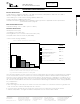
Single Contact
18 AWG
[0.8 mm
2
]
Ambient Temperature (°C)
Current Rating (Amperes)
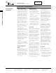
18
20
22
24
26
Single
1
.83
.69
.59
.50
30%
.97
.80
.66
.57
.49
50%
.83
.68
.57
.48
.42
70%
.65
.53
.45
.38
.33
100%
.55
.45
.38
.32
.28
AWG
% Loading
Figure 1
Graph shows the relationship between base current, ambient tem-
perature, and contact T-rise.
Figure 2
Rating factors allow the base current to be adjusted for various con-
nector loading and wire sizes.
An Example:
To demonstrate the method of specifying current, consider the
following application conditions, an ambient temperature of
65°C, a 50% loading of contacts in the housing, and 20 AWG
[0.6 mm2] wire.
From Figure 1, the base current rating is 14 ampere with 18 •
AWG [0.8 mm2] wire.
Figure 2, the rating factor for 50% loading and 20 AWG [0.6 •
mm2] wire is 0.68.
The specific rating for this application is the product of the •
base rating and the rating factor:
14 x 0.68 = 9.5 ampere
Each of the contacts can carry 9.5 ampere.•
However, if the ambient temperature is 80• °C the allowable
T-rise becomes 25°C. The base current must be lowered to
12.8 ampere so that the 105
°C maximum operating tempera-
ture is not exceeded. The current rating then becomes:
12.8 x 0.68 = 8.7 ampere.
Performance Characteristics (Continued)
Performance Characteristics