
Datasheet

Specifications and availability subject to change without notice.
13C8920 Printed in U.S.A. IH/3-00
Tyco Electronics Corporation - P&B, Winston-Salem, NC 27102
Technical Support Center: 1-800-522-6752, www.pandbrelays.com
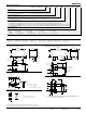
Wiring Diagram
2
6
34
78
0
1
Only necessary terminals are
present on single throw models.
Note: An alternate PC board layout utilizes .076 ± .003 (1.93 ± .076) diameter holes on the
same center-to-center spacing shown above. Use of the rectangular holes is
recommended for improved solderability.
Suggested PC Board Layout (Bottom View)
1.618
(41.10)
.585
(14.86)
.309
(7.85)
.630
(16.00)
.203 TYP.
(5.16)
.052 TYP.
(1.32)
.072 TYP.
(1.83)
1.000
(25.40)
.162
(4.12)
.365
(9.27)
.185
(4.70)
1. 6 7
(42.41)
.50
(12.7)
.50
(12.7)
.20
(5.08)
.40
(10.16)
.79
(20.06)
3 Holes for #6-32 Screw
0.011 Deep
(.27)
DIN Mount Adapter - 9T91A001
Note: Fits 35mm din track
Includes: 2 Din clips
2 Screws
Must be ordered in multiples of 50.
Mounting & Termination Type 1
Outline Dimensions
Mounting & Termination Types 2, 3 & 4
2.700 MAX.
(68.58)
2.05 MAX.
(52.07)
1.618 TYP.
(41.10 ± .51)
.585 ± .005
(14.86 ± .13)
.309 ± .005
(7.85 ± .13)
1.36 MAX.
(34.54)
1.04 MAX.
(26.42)
.630 TYP.
(16.00)
2.35 ± .005
(59.71 ± .13)
.090 RAD.
(2.29)
FOR #8 SCREW
1.495 MAX.
(37.97)
2.06 MAX.
(52.32)
1.618 ± .020
(41.10 ± .51)
.585 ± .005
(14.86 ± .13)
.309 ± .005
(7.85 ± .13)
1.36 MAX.
(34.54)
1.21 MAX.
(30.73)
.630 ± .005
(16.00 ± .13)
.156
(3.96)
.250 TYP.
(6.35)
1.000 ± .010
(25.40 ± .25)
.032 TYP.
(0.81)
.047 TYP.
(1.19)
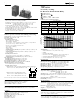
Stock Items – We recommend that our authorized distributors stock the following items for immediate delivery.
T92P7D12-24
T92P7D22-12
T92P7D22-24
T92P11A22-24
T92P7A22-240
T92P7D12-12
T92P7A22-24
T92P7A22-120
T92P11D22-12
T92P11D22-24
T92P11A22-120
T92P11A22-240
Ordering Information
Typical Part Number B T92 S 11 D 2 2 -24
1. Basic Series:
T92 = Printed circuit board / panel mount power relay.
2. Enclosure:
P = Plastic dust cover (unsealed). S = Immersion cleanable, tape sealed plastic case (code 1).
3. Contact Arrangement:
7 = 2 form A (DPST-NO). 11 = 2 form C (DPDT).
4. Coil Input:
A = AC voltage, 60 Hz. or 50/60 Hz. (See Coil Data Table) D = DC voltage.
5. Mounting & Termination:
1 = Printed circuit board mount; printed circuit board terminals for coil and contacts.
2 = Panel mount via flanged cover; .250” (6.35mm)
x .032” (.81mm)
quick connect terminals for coil and contacts.
3 =
Panel mount via flanged cover; .187” (4.75mm) x .032” (.81mm) quick connect terminals for coil and .250” (6.35mm) for contacts.
4 =
Panel mount via flanged cover, .187” (4.75mm) x .020” (.51mm) quick connect terminals for coil and .250” (6.35mm) for contacts.
6. Contact Material:
2 = Silver cadmium oxide.
7. Coil Voltage: (See Coil Data Table)
(DC) 12 = 12VDC 24 = 24VDC 48 = 48VDC 110 = 110VDC
(60Hz.) 12 = 12VAC 24 = 24VAC
(50/60Hz.) 110 = 100/110VAC 120 = 110/120VAC 240 = 220/240VAC 277 = 250/277VAC
T92S7D12-12
T92S7D12-24
T92S11D22-12
T92S11D22-24