
User manual


Instruction Sheet
S
OLARLOK
Interconnection System
411-18305-1
26 JUL 2011 Rev. G
TE CONNECTIVITY,
Harrisburg, PA 17105
*
Trademark
| Indicates change
http://www.tycoelectronics.com/solar/
This specification is a controlled document.
Copyright 2011 by TE CONNECTIVITY.
All rights reserved
2
of
7
ECOC EGD0
LOC: AI
4. Accessories
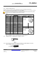
4.1. T-Distributor
The T-Distributor is used for connecting a parallel circuit or coupling. Take care to ensure that the max.
overall current is not exceed. The T-Distributer must always be fully completely connected!
CAUTION: Do not disconnect the connector under load (see 5.3.4)!
Disconnect circuit from load before unplugging connectors.
Cable assemblies should be labeled using Label 1718077-1.
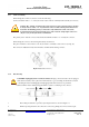
4.2. Interlock Clip and S
OLARLOK
Locking Collar
For application of the interlock clip and the application of the S
OLARLOK
Locking Collar see Instruction
Sheet 408-10296
Figure 1 a: Figure1b:
5. Assembly Procedure for S
OLARLOK
Plug connector
CAUTION: This connector must be used only to interconnect firmly fixed cables.
Do not disconnect under load.
Current path must only be disconnected using approved disconnect devices.
Cable assemblies shall be labeled with PN 1718077-1.
To protect against shock, ensure that conductors and their associated connectors are separated from
opposite polarity components.
5.1. Caution any kind of pollution (dust, humidity, etc.) during the assembly process can degrade contact and
connector performance. This applies in particular to the seals and the crimping of the contacts. A clean/dry
assembly environment is therefore essential.
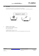
5.2. Termination of the cable wires / crimping of the contacts
The connectors accept different contacts for various wire gauges. Possible wire gauges are 2.5 mm², 4.0 mm²
and 6mm² (6mm² only Tyco Electronics Solar wire), 14 AWG, 12 AWG, and 10 AWG. The tools to be used
are selected based upon the wire gauge. For the application specification, please refer to 114-94061.