
User manual


Instruction Sheet
SOLARLOK Interconnection System
411-18305-1
26 JUL 2011 Rev. G
TE CONNECTIVITY,
Harrisburg, PA 17105
*
Trademark
| Indicates change
http://www.tycoelectronics.com/solar/
This specification is a controlled document.
Copyright 2011 by TE CONNECTIVITY.
All rights reserved
5 of 7
ECOC EGD0
LOC: AI
For further information, please refer to TE Application Specification 114-94061.
Make sure that the contact is correctly positioned in the applicator or hand tool. For easier handling, use the
locator.
For pre-assembled connectors, start with chapter 5.3.2.4
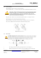
5.3.2.2 Press seal into the connector housing until it stops (see Fig. 5 and 6).
Figure 5 Components of connector housing
Figure 6 Pre assembled seal
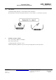
5.3.2.3 Screw backshell nut onto connector housing (2 to 3 turns max. see Fig. 7)
Figure 7 Assembled Connector Housing
5.3.2.4 Push contact with cable into the connector housing until you hear the contact click into plastic housing;
pull back slightly to ensure the contact is locked (Figure 8)
Figure 8 Contact assembly
5.3.2.5 Screw backshell nut with a torque wrench with slotted insert (TE-PN: 523229-1) onto the connector
h
ousing. Tighten backshell nut to an initial torque of max. 1.3
+0.2
Nm (see Fig. 9 and 10)
Figure 9 Figure 10
Tighten back shell nut to a initial torque of max. 1.3
+0 2
Nm Label female connector with label
“Do not disconnect under load”.