
Datasheet


09-2017, Rev. 0917
www.te.com
© 2015 Tyco Electronics Corporation,
a TE Connectivity Ltd. company
Datasheets and product specification
according to IEC 61810-1 and to be used
only together with the ‘Definitions’ section.
Datasheets and product data is subject to the
terms of the disclaimer and all chapters of
the ‘Definitions’ section, available at
http://relays.te.com/definitions
Datasheets, product data, ‘Definitions’ sec-
tion, application notes and all specifications
are subject to change.
2
AXICOM
Signal Relays
IM Relay (Continued)
Insulation Data standard* C* D,P, I
standard, high high current,
sensitive, dielectric high contact
ultra high version stability
sensitive version
version
Initial dielectric strength
between open contacts 1000V
rms
1500V
rms
750V
rms
between contact and coil 1800V
rms
1800V
rms
1500V
rms
between adjacent contacts 1000V
rms
1800V
rms
750V
rms
Initial surge withstand voltage
between open contacts 1500V 2500V 1000V
between contact and coil 2500V 2500V 2000V
between adjacent contacts 1500V 2500V 1000V
Initial insulation resistance
between insulated elements >10
9
Ω >10
9
Ω >10
9
Ω
Capacitance
between open contacts max. 1pF
between contact and coil max. 2pF
between adjacent contacts max. 2p
RF Data
Isolation at 100MHz/900MHz 37.0dB/18.8dB
Insertion loss at 100MHz/900MHz 0.03dB/0.33dB
Voltage standing wave ratio (VSWR)
at 100MHz/900MHz 1.06/1.49
Other Data
Material compliance: EU RoHS/ELV, China RoHS, REACH, Halogen content
refer to the Product Compliance Support Center at
www.te.com/customersupport/rohssupportcenter
Ambient temperature -40°C to +85°C
Thermal resistance <150K/W
Category of environmental protection
IEC 61810 RT V - hermetically sealed
Vibration resistance (functional) 20g, 10 to 500Hz
Shock resistance (functional), half sinus 11ms 50g
Shock resistance (destructive), half sinus 0.5ms 500g
Mounting position any
Weight max. 0.75g
Resistance to soldering heat SMT
IEC 60068-2-58
Moisture sensitive level, JEDEC J-Std-020D MSL3
related only to SMT relays
packed in orginal dry-packs
Ultrasonic cleaning not recommended
Packaging/unit
THT version tube/50pcs., box/1000 pcs.
SMT version
reel/1000 pcs., box/1000 or 5000 pcs.
Coil Data (continued)
Coil versions, sensitive version, monostable, 1 coil
Coil Rated Operate Release Coil Rated coil
code voltage voltage voltage resistance power
VDC VDC VDC Ω±10% mW
11 3 2.40 0.30 91 100
12 4.5 3.60 0.45 194 100
13 5 4.00 0.50 234 100
16 12 9.60 1.20 1315 110
17 24 19.20 2.40 4120 140
Coil versions, ultra high sensitive version, monostable, 1 coil
Coil Rated Operate Release Coil Rated coil
code voltage voltage voltage resistance power
VDC VDC VDC Ω±10% mW
21 3 3.00 0.30 180 50
22 4.5 4.50 0.45 405 50
23 5 5.00 0.50 500 50
26 12 12.00 1.20 2880 50
All figures are given for coil without pre-energization, at ambient temperature +23°C
Coil versions, standard, bistable 1 coil
Coil Rated Set Reset Coil Rated coil
code voltage voltage voltage resistance power
VDC VDC VDC Ω±10% mW
40 1.5 1.13 -1.13 23 100
48 2.4 1.80 -1.80 58 100
41 3 2.25 -2.25 90 100
42 4.5 3.38 -3.38 203 100
43 5 3.75 -3.75 250 100
44 6 4.50 -4.50 360 100
45 9 6.75 -6.75 810 100
46 12 9.00 -9.00 1440 100
47 24 18.00 -18.00 2880 200
All figures are given for coil without pre-energization, at ambient temperature +23°C
108-98001 Rev. M
All specifications subject to change. Consult Tyco Electronics for latest specifications. 24 of 28
AXICOMÊSignalÊRelays
IM Relay
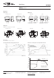
Coil Operating Range
U
nom
= Nominal coil voltage
U
max.
= Upper limit of the operative range of
the coil voltage (limiting voltage) when
coils are continously energized
U
op. min.
= Lower limit of the operative range of
the coil voltage (reliable operate voltage)
For latching relays Uset min. resp.
Ureset min.
U
rel. min.
= Lower limit of the operative range of
the coil voltage (reliable release voltage)
0
0. 2
0. 4
0. 6
0. 8
1
1. 2
1. 4
1. 6
1. 8
2
2. 2
2. 4
2. 6
2. 8
3
3. 2
3. 4
-50-40 -30-20 -100 10 20 30 40 50 60 70 80 90 10 0110 12 0
Coil Voltage [U/Unom]
Umax. at 0A
Umax. at 2x2A
Umax. at 2x1A
Unom. nominal coil voltage
Ambient Temperature [°C]
0
0.2
0.4
0.6
0.8
1
1.2
1.4
1.6
1.8
2
2.2
2.4
2.6
2.8
3
3.2
3.4
-50 -40 -30 -20 -10 0102030405060708090 100 110 120
Ambient Temperature [°C]
Coil Voltage [U/Unom
]
Umax. at 0A
Umax. at 2x2A
Umax. at 2x1A
Unom. nominal coil voltage
Urel. min.
0
0.2
0.4
0.6
0.8
1
1.2
1.4
1.6
1.8
2
2.2
2.4
2.6
2.8
3
3.2
3.4
-50-40 -30-20 -100 10 20 30 40 50 60 70 80 90 100 110 120 130 140
Ambient Temperature [°C]
Coil Voltage [U/Unom
]
Umax. - 5%coil
duty at
2x2A (100mW)
U
max
.-5%coil
duty at 0A(100mW)
Umax.-5%coil
duty at 0A (200mW)
Umax. -5% coil
duty at 2x1A (100mW)
Unom. nominal coil voltage
Umax. at 0A
140mW coil
200mW coil
Urel. min.
50mW coil
100mW coil
Uop min.
U
max.
at 0A
Umax. - 100% coil duty at
0A (100mW)
Umax. - 100% coil duty at
0A (200mW)
Uset min.
100 mW Latching
200 mW Latching
Coil operating range, sensitive and ultra high sensitive coil
108-98001 Rev. M
All specifications subject to change. Consult Tyco Electronics for latest specifications. 24 of 28
AXICOMÊSignalÊRelays
IM Relay
Coil Operating Range
U
nom
= Nominal coil voltage
U
max.
= Upper limit of the operative range of
the coil voltage (limiting voltage) when
coils are continously energized
U
op. min.
= Lower limit of the operative range of
the coil voltage (reliable operate voltage)
For latching relays Uset min. resp.
Ureset min.
U
rel. min.
= Lower limit of the operative range of
the coil voltage (reliable release voltage)
0
0. 2
0. 4
0. 6
0. 8
1
1. 2
1. 4
1. 6
1. 8
2
2. 2
2. 4
2. 6
2. 8
3
3. 2
3. 4
-50-40 -30-20 -100 10 20 30 40 50 60 70 80 90 10 0110 12 0
Coil Voltage [U/Unom]
Umax. at 0A
Umax. at 2x2A
Umax. at 2x1A
U
nom.
nominal coil voltage
Ambient Temperature [°C]
0
0.2
0.4
0.6
0.8
1
1.2
1.4
1.6
1.8
2
2.2
2.4
2.6
2.8
3
3.2
3.4
-50 -40 -30 -20 -10 0102030405060708090 100 110 120
Ambient Temperature [°C]
Coil Voltage [U/Unom
]
Umax. at 0A
Umax. at 2x2A
Umax. at 2x1A
Unom. nominal coil voltage
Urel. min.
0
0.2
0.4
0.6
0.8
1
1.2
1.4
1.6
1.8
2
2.2
2.4
2.6
2.8
3
3.2
3.4
-50-40 -30-20 -100 10 20 30 40 50 60 70 80 90 100 110 120 130 140
Ambient Temperature [°C]
Coil Voltage [U/U
nom
]
U
max
. - 5%coil
duty at
2x2A (100mW)
U
max
.-5%coil
duty at 0A(100mW)
Umax.-5%coil
duty at 0A (200mW)
Umax. -5% coil
duty at 2x1A (100mW)
U
nom.
nominal coil voltage
Umax. at 0A
140mW coil
200mW coil
Urel. min.
50mW coil
100mW coil
Uop min.
Umax. at 0A
Umax. - 100% coil duty at
0A (100mW)
Umax. - 100% coil duty at
0A (200mW)
Uset min.
100 mW Latching
200 mW Latching
Coil operating range, bistable 1 coil
Monostable version
rest condition
108-98001 Rev. M
All specifications subject to change. Consult Tyco Electronics for latest specifications. 5 of 28
AXICOMÊSignalÊRelays
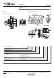
IM Relay 2 Pole Changeover / 2 Form C / DPDT
Dimensions Dimensions in mm
THT Version
Mounting Hole Layout
View onto the component side of the PCB (top view)
Non-Latching Type
not energized condition
Latching Type, 1 Coil
reset condition
IMÊTHT
Standard
IMÊTHT
Narrow
IMÊSMT
GullÊWings
IMÊSMT
J-Legs
mm inch mm inch mm inch mm inch
L
W
H
10.00ʱÊ0.08
6.00ʱÊ0.08
5.65ÊÐÊ0.20
0.393ʱÊ0.003
0.236ʱÊ0.003
0.222ÊÐÊ0.008
10.00ʱÊ0.08
5.70ʱÊ0.30
5.80ʱÊ0.08
0.393ʱÊ0.003
0.224ʱÊ0.012
0.230ʱÊ0.003
10.00ʱÊ0.08
ÊÊ6.00ʱÊ0.08
ÊÊ5.65ÊÐÊ0.20
0.393ʱÊ0.003
0.236ʱÊ0.003
0.222ÊÐÊ0.008
10.00ʱÊ0.08
ÊÊ6.00ʱÊ0.08
ÊÊ5.65ÊÐÊ0.02
0.393ʱÊ0.003
0.236ʱÊ0.003
0.222ÊÐÊ0.008
SMT Version
Standard Version
Narrow Version
Solder Pad Layout
View onto the component side of the PCB (top view)
Gull Wings J-Legs
Standard Version
Narrow Version
Gull Wings
¯Êmin.Ê0.75
¯Êmin.Ê0.75
Terminal Assignment
Relay – top view
ContactsÊ inÊresetÊ position.Ê ContactÊ
positionÊ mightÊ changeÊ duringÊ trans-
portationÊ andÊ mustÊ beÊresetÊ beforeÊ
use.
Coplanarity ≤ 0.1mm
Coplanarity ≤ 0.1mm
T
T1
T2
D1
D2
Tw
S
3.2
N/A
5.08ʱÊ0.10
3.20ʱÊ0.15
2.20ʱÊ0.15
0.40
0.75
0.125
N/A
0.200ʱÊ0.004
0.126ʱÊ0.006
0.087ʱÊ0.006
0.015
0.029
3.2
N/A
3.20ʱÊ0.10
3.20ʱÊ0.15
2.20ʱÊ0.15
0.4
0.30ʱÊ0.05
0.125
N/A
0.126ʱÊ0.004
0.126ʱÊ0.006
0.087ʱÊ0.006
0.015
0.011ʱÊ0.002
N/A
7.50ʱÊ0.30
5.08ʱÊ0.10
3.20ʱÊ0.15
2.20ʱÊ0.15
0.4
N/A
N/A
0.295ʱÊ0.011
0.200ʱÊ0.004
0.126ʱÊ0.006
0.087ʱÊ0.006
0.015
N/A
N/A
2.80ʱÊ0.20
5.08ʱÊ0.10
3.20ʱÊ0.15
2.20ʱÊ0.15
0.4
N/A
N/A
0.110ʱÊ0.007
0.200ʱÊ0.004
0.126ʱÊ0.006
0.087ʱÊ0.006
0.015
N/A
10.0±0.08
6.0±0.08
5.08±0.1
0.4
3.2±0.15
2.2±0.15
2.2±0.15
3.2
5.65-0.2
0.75
10.0±0.08
5.7±0.3
3.2±0.1
0.4
3.2±0.15
2.2±0.15
2.2±0.15
3.2
5.8±0.08
0.3±0.05
10.0±0.08
6.0±0.08
5.08±0.1
0.4
3.2±0.15
2.2±0.15
2.2±0.15
5.65-0.2
10.0±0.08
6.0±0.08
5.08±0.1
0.4
3.2±0.15
2.2±0.15
2.2±0.15
5.65-0.2
7.5±0.3
Coplanarity ≤0.1mm
2.8±0.2
Coplanarity ≤0.1mm
Bistable version, 1 coil
reset condition
108-98001 Rev. M
All specifications subject to change. Consult Tyco Electronics for latest specifications. 5 of 28
AXICOMÊSignalÊRelays
IM Relay 2 Pole Changeover / 2 Form C / DPDT
Dimensions Dimensions in mm
THT Version
Mounting Hole Layout
View onto the component side of the PCB (top view)
Non-Latching Type
not energized condition
Latching Type, 1 Coil
reset condition
IMÊTHT
Standard
IMÊTHT
Narrow
IMÊSMT
GullÊWings
IMÊSMT
J-Legs
mm inch mm inch mm inch mm inch
L
W
H
10.00ʱÊ0.08
6.00ʱÊ0.08
5.65ÊÐÊ0.20
0.393ʱÊ0.003
0.236ʱÊ0.003
0.222ÊÐÊ0.008
10.00ʱÊ0.08
5.70ʱÊ0.30
5.80ʱÊ0.08
0.393ʱÊ0.003
0.224ʱÊ0.012
0.230ʱÊ0.003
10.00ʱÊ0.08
ÊÊ6.00ʱÊ0.08
ÊÊ5.65ÊÐÊ0.20
0.393ʱÊ0.003
0.236ʱÊ0.003
0.222ÊÐÊ0.008
10.00ʱÊ0.08
ÊÊ6.00ʱÊ0.08
ÊÊ5.65ÊÐÊ0.02
0.393ʱÊ0.003
0.236ʱÊ0.003
0.222ÊÐÊ0.008
SMT Version
Standard Version
Narrow Version
Solder Pad Layout
View onto the component side of the PCB (top view)
Gull Wings J-Legs
Standard Version
Narrow Version
Gull Wings
¯Êmin.Ê0.75
¯Êmin.Ê0.75
Terminal Assignment
Relay – top view
ContactsÊ inÊresetÊ position.Ê ContactÊ
positionÊ mightÊ changeÊ duringÊ trans-
portationÊ andÊ mustÊ beÊresetÊ beforeÊ
use.
Coplanarity ≤ 0.1mm
Coplanarity ≤ 0.1mm
T
T1
T2
D1
D2
Tw
S
3.2
N/A
5.08ʱÊ0.10
3.20ʱÊ0.15
2.20ʱÊ0.15
0.40
0.75
0.125
N/A
0.200ʱÊ0.004
0.126ʱÊ0.006
0.087ʱÊ0.006
0.015
0.029
3.2
N/A
3.20ʱÊ0.10
3.20ʱÊ0.15
2.20ʱÊ0.15
0.4
0.30ʱÊ0.05
0.125
N/A
0.126ʱÊ0.004
0.126ʱÊ0.006
0.087ʱÊ0.006
0.015
0.011ʱÊ0.002
N/A
7.50ʱÊ0.30
5.08ʱÊ0.10
3.20ʱÊ0.15
2.20ʱÊ0.15
0.4
N/A
N/A
0.295ʱÊ0.011
0.200ʱÊ0.004
0.126ʱÊ0.006
0.087ʱÊ0.006
0.015
N/A
N/A
2.80ʱÊ0.20
5.08ʱÊ0.10
3.20ʱÊ0.15
2.20ʱÊ0.15
0.4
N/A
N/A
0.110ʱÊ0.007
0.200ʱÊ0.004
0.126ʱÊ0.006
0.087ʱÊ0.006
0.015
N/A
10.0±0.08
6.0±0.08
5.08±0.1
0.4
3.2±0.15
2.2±0.15
2.2±0.15
3.2
5.65-0.2
0.75
10.0±0.08
5.7±0.3
3.2±0.1
0.4
3.2±0.15
2.2±0.15
2.2±0.15
3.2
5.8±0.08
0.3±0.05
10.0±0.08
6.0±0.08
5.08±0.1
0.4
3.2±0.15
2.2±0.15
2.2±0.15
5.65-0.2
10.0±0.08
6.0±0.08
5.08±0.1
0.4
3.2±0.15
2.2±0.15
2.2±0.15
5.65-0.2
7.5±0.3
Coplanarity ≤0.1mm
2.8±0.2
Coplanarity ≤0.1mm
Contacts are shown in reset condition. Contact position might change during
transportation and must be reset before use.
*this relay contains SF6 (Sulfur hexafluoride, CAS number: 2551-62-4) for dielectric strength
enhancement, SF6 is hermetically sealed in relay without leaks to air during normal applica-
tion as recommended per the applicable product specification. It is clarified that the usage
of SF6 in mini signal relay is not prohibited by related regulations. Please contact TE local
sales or field engineer for further information and detailed material declaration.