
Datasheet


09-2017, Rev. 0917
www.te.com
© 2015 Tyco Electronics Corporation,
a TE Connectivity Ltd. company
Datasheets and product specification
according to IEC 61810-1 and to be used
only together with the ‘Definitions’ section.
Datasheets and product data is subject to the
terms of the disclaimer and all chapters of
the ‘Definitions’ section, available at
http://relays.te.com/definitions
Datasheets, product data, ‘Definitions’ sec-
tion, application notes and all specifications
are subject to change.
3
AXICOM
Signal Relays
IM Relay (Continued)
THT version
Dimensions
108-98001 Rev. M
All specifications subject to change. Consult Tyco Electronics for latest specifications. 5 of 28
AXICOMÊSignalÊRelays
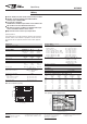
IM Relay 2 Pole Changeover / 2 Form C / DPDT
Dimensions Dimensions in mm
THT Version
Mounting Hole Layout
View onto the component side of the PCB (top view)
Non-Latching Type
not energized condition
Latching Type, 1 Coil
reset condition
IMÊTHT
Standard
IMÊTHT
Narrow
IMÊSMT
GullÊWings
IMÊSMT
J-Legs
mm inch mm inch mm inch mm inch
L
W
H
10.00ʱÊ0.08
6.00ʱÊ0.08
5.65ÊÐÊ0.20
0.393ʱÊ0.003
0.236ʱÊ0.003
0.222ÊÐÊ0.008
10.00ʱÊ0.08
5.70ʱÊ0.30
5.80ʱÊ0.08
0.393ʱÊ0.003
0.224ʱÊ0.012
0.230ʱÊ0.003
10.00ʱÊ0.08
ÊÊ6.00ʱÊ0.08
ÊÊ5.65ÊÐÊ0.20
0.393ʱÊ0.003
0.236ʱÊ0.003
0.222ÊÐÊ0.008
10.00ʱÊ0.08
ÊÊ6.00ʱÊ0.08
ÊÊ5.65ÊÐÊ0.02
0.393ʱÊ0.003
0.236ʱÊ0.003
0.222ÊÐÊ0.008
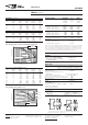
SMT Version
Standard Version
Narrow Version
Solder Pad Layout
View onto the component side of the PCB (top view)
Gull Wings J-Legs
Standard Version
Narrow Version
Gull Wings
¯Êmin.Ê0.75
¯Êmin.Ê0.75
Terminal Assignment
Relay – top view
ContactsÊ inÊresetÊ position.Ê ContactÊ
positionÊ mightÊ changeÊ duringÊ trans-
portationÊ andÊ mustÊ beÊresetÊ beforeÊ
use.
Coplanarity ≤ 0.1mm
Coplanarity ≤ 0.1mm
T
T1
T2
D1
D2
Tw
S
3.2
N/A
5.08ʱÊ0.10
3.20ʱÊ0.15
2.20ʱÊ0.15
0.40
0.75
0.125
N/A
0.200ʱÊ0.004
0.126ʱÊ0.006
0.087ʱÊ0.006
0.015
0.029
3.2
N/A
3.20ʱÊ0.10
3.20ʱÊ0.15
2.20ʱÊ0.15
0.4
0.30ʱÊ0.05
0.125
N/A
0.126ʱÊ0.004
0.126ʱÊ0.006
0.087ʱÊ0.006
0.015
0.011ʱÊ0.002
N/A
7.50ʱÊ0.30
5.08ʱÊ0.10
3.20ʱÊ0.15
2.20ʱÊ0.15
0.4
N/A
N/A
0.295ʱÊ0.011
0.200ʱÊ0.004
0.126ʱÊ0.006
0.087ʱÊ0.006
0.015
N/A
N/A
2.80ʱÊ0.20
5.08ʱÊ0.10
3.20ʱÊ0.15
2.20ʱÊ0.15
0.4
N/A
N/A
0.110ʱÊ0.007
0.200ʱÊ0.004
0.126ʱÊ0.006
0.087ʱÊ0.006
0.015
N/A
10.0±0.08
6.0±0.08
5.08±0.1
0.4
3.2±0.15
2.2±0.15
2.2±0.15
3.2
5.65-0.2
0.75
10.0±0.08
5.7±0.3
3.2±0.1
0.4
3.2±0.15
2.2±0.15
2.2±0.15
3.2
5.8±0.08
0.3±0.05
10.0±0.08
6.0±0.08
5.08±0.1
0.4
3.2±0.15
2.2±0.15
2.2±0.15
5.65-0.2
10.0±0.08
6.0±0.08
5.08±0.1
0.4
3.2±0.15
2.2±0.15
2.2±0.15
5.65-0.2
7.5±0.3
Coplanarity ≤0.1mm
2.8±0.2
Coplanarity ≤0.1mm
SMT version
108-98001 Rev. M
All specifications subject to change. Consult Tyco Electronics for latest specifications. 5 of 28
AXICOMÊSignalÊRelays
IM Relay 2 Pole Changeover / 2 Form C / DPDT
Dimensions Dimensions in mm
THT Version
Mounting Hole Layout
View onto the component side of the PCB (top view)
Non-Latching Type
not energized condition
Latching Type, 1 Coil
reset condition
IMÊTHT
Standard
IMÊTHT
Narrow
IMÊSMT
GullÊWings
IMÊSMT
J-Legs
mm inch mm inch mm inch mm inch
L
W
H
10.00ʱÊ0.08
6.00ʱÊ0.08
5.65ÊÐÊ0.20
0.393ʱÊ0.003
0.236ʱÊ0.003
0.222ÊÐÊ0.008
10.00ʱÊ0.08
5.70ʱÊ0.30
5.80ʱÊ0.08
0.393ʱÊ0.003
0.224ʱÊ0.012
0.230ʱÊ0.003
10.00ʱÊ0.08
ÊÊ6.00ʱÊ0.08
ÊÊ5.65ÊÐÊ0.20
0.393ʱÊ0.003
0.236ʱÊ0.003
0.222ÊÐÊ0.008
10.00ʱÊ0.08
ÊÊ6.00ʱÊ0.08
ÊÊ5.65ÊÐÊ0.02
0.393ʱÊ0.003
0.236ʱÊ0.003
0.222ÊÐÊ0.008
SMT Version
Standard Version
Narrow Version
Solder Pad Layout
View onto the component side of the PCB (top view)
Gull Wings J-Legs
Standard Version
Narrow Version
Gull Wings
¯Êmin.Ê0.75
¯Êmin.Ê0.75
Terminal Assignment
Relay – top view
ContactsÊ inÊresetÊ position.Ê ContactÊ
positionÊ mightÊ changeÊ duringÊ trans-
portationÊ andÊ mustÊ beÊresetÊ beforeÊ
use.
Coplanarity ≤ 0.1mm
Coplanarity ≤ 0.1mm
T
T1
T2
D1
D2
Tw
S
3.2
N/A
5.08ʱÊ0.10
3.20ʱÊ0.15
2.20ʱÊ0.15
0.40
0.75
0.125
N/A
0.200ʱÊ0.004
0.126ʱÊ0.006
0.087ʱÊ0.006
0.015
0.029
3.2
N/A
3.20ʱÊ0.10
3.20ʱÊ0.15
2.20ʱÊ0.15
0.4
0.30ʱÊ0.05
0.125
N/A
0.126ʱÊ0.004
0.126ʱÊ0.006
0.087ʱÊ0.006
0.015
0.011ʱÊ0.002
N/A
7.50ʱÊ0.30
5.08ʱÊ0.10
3.20ʱÊ0.15
2.20ʱÊ0.15
0.4
N/A
N/A
0.295ʱÊ0.011
0.200ʱÊ0.004
0.126ʱÊ0.006
0.087ʱÊ0.006
0.015
N/A
N/A
2.80ʱÊ0.20
5.08ʱÊ0.10
3.20ʱÊ0.15
2.20ʱÊ0.15
0.4
N/A
N/A
0.110ʱÊ0.007
0.200ʱÊ0.004
0.126ʱÊ0.006
0.087ʱÊ0.006
0.015
N/A
10.0±0.08
6.0±0.08
5.08±0.1
0.4
3.2±0.15
2.2±0.15
2.2±0.15
3.2
5.65-0.2
0.75
10.0±0.08
5.7±0.3
3.2±0.1
0.4
3.2±0.15
2.2±0.15
2.2±0.15
3.2
5.8±0.08
0.3±0.05
10.0±0.08
6.0±0.08
5.08±0.1
0.4
3.2±0.15
2.2±0.15
2.2±0.15
5.65-0.2
10.0±0.08
6.0±0.08
5.08±0.1
0.4
3.2±0.15
2.2±0.15
2.2±0.15
5.65-0.2
7.5±0.3
Coplanarity ≤0.1mm
2.8±0.2
Coplanarity ≤0.1mm
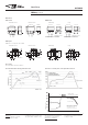
Standard version Narrow version Gull wings J-legs
PCB layout
TOP view on component side of PCB
Standard version Narrow version Gull wings J-legs
108-98001 Rev. M
All specifications subject to change. Consult Tyco Electronics for latest specifications. 5 of 28
AXICOMÊSignalÊRelays
IM Relay 2 Pole Changeover / 2 Form C / DPDT
Dimensions Dimensions in mm
THT Version
Mounting Hole Layout
View onto the component side of the PCB (top view)
Non-Latching Type
not energized condition
Latching Type, 1 Coil
reset condition
IMÊTHT
Standard
IMÊTHT
Narrow
IMÊSMT
GullÊWings
IMÊSMT
J-Legs
mm inch mm inch mm inch mm inch
L
W
H
10.00ʱÊ0.08
6.00ʱÊ0.08
5.65ÊÐÊ0.20
0.393ʱÊ0.003
0.236ʱÊ0.003
0.222ÊÐÊ0.008
10.00ʱÊ0.08
5.70ʱÊ0.30
5.80ʱÊ0.08
0.393ʱÊ0.003
0.224ʱÊ0.012
0.230ʱÊ0.003
10.00ʱÊ0.08
ÊÊ6.00ʱÊ0.08
ÊÊ5.65ÊÐÊ0.20
0.393ʱÊ0.003
0.236ʱÊ0.003
0.222ÊÐÊ0.008
10.00ʱÊ0.08
ÊÊ6.00ʱÊ0.08
ÊÊ5.65ÊÐÊ0.02
0.393ʱÊ0.003
0.236ʱÊ0.003
0.222ÊÐÊ0.008
SMT Version
Standard Version
Narrow Version
Solder Pad Layout
View onto the component side of the PCB (top view)
Gull Wings J-Legs
Standard Version
Narrow Version
Gull Wings
¯Êmin.Ê0.75
¯Êmin.Ê0.75
Terminal Assignment
Relay – top view
ContactsÊ inÊresetÊ position.Ê ContactÊ
positionÊ mightÊ changeÊ duringÊ trans-
portationÊ andÊ mustÊ beÊresetÊ beforeÊ
use.
Coplanarity ≤ 0.1mm
Coplanarity ≤ 0.1mm
T
T1
T2
D1
D2
Tw
S
3.2
N/A
5.08ʱÊ0.10
3.20ʱÊ0.15
2.20ʱÊ0.15
0.40
0.75
0.125
N/A
0.200ʱÊ0.004
0.126ʱÊ0.006
0.087ʱÊ0.006
0.015
0.029
3.2
N/A
3.20ʱÊ0.10
3.20ʱÊ0.15
2.20ʱÊ0.15
0.4
0.30ʱÊ0.05
0.125
N/A
0.126ʱÊ0.004
0.126ʱÊ0.006
0.087ʱÊ0.006
0.015
0.011ʱÊ0.002
N/A
7.50ʱÊ0.30
5.08ʱÊ0.10
3.20ʱÊ0.15
2.20ʱÊ0.15
0.4
N/A
N/A
0.295ʱÊ0.011
0.200ʱÊ0.004
0.126ʱÊ0.006
0.087ʱÊ0.006
0.015
N/A
N/A
2.80ʱÊ0.20
5.08ʱÊ0.10
3.20ʱÊ0.15
2.20ʱÊ0.15
0.4
N/A
N/A
0.110ʱÊ0.007
0.200ʱÊ0.004
0.126ʱÊ0.006
0.087ʱÊ0.006
0.015
N/A
10.0±0.08
6.0±0.08
5.08±0.1
0.4
3.2±0.15
2.2±0.15
2.2±0.15
3.2
5.65-0.2
0.75
10.0±0.08
5.7±0.3
3.2±0.1
0.4
3.2±0.15
2.2±0.15
2.2±0.15
3.2
5.8±0.08
0.3±0.05
10.0±0.08
6.0±0.08
5.08±0.1
0.4
3.2±0.15
2.2±0.15
2.2±0.15
5.65-0.2
10.0±0.08
6.0±0.08
5.08±0.1
0.4
3.2±0.15
2.2±0.15
2.2±0.15
5.65-0.2
7.5±0.3
Coplanarity ≤0.1mm
2.8±0.2
Coplanarity ≤0.1mm
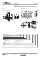
Recommended soldering conditions
Processing
Recommended reflow soldering profile IEC 61760-1
full line: typical
dotted line: process limits
external preheating
240°C
180°C
130°C
100°C
forced cooling
20 to 40s
Time [s]
Temperature [°C]
Vapour phase soldering
temperature/time profile
(lead and housing peak temp.)
Recommended soldering conditions
Vapour phase soldering
Resistance to soldering heat - reflow profile IEC 60068-2-58