
User manual

1 of 10
© 2014 TE Connectivity family of companies
All Rights Reserved
*Trademark
TE Connectivity, TE connectivity (logo), and TE (logo) are trademarks. Other logos, product, and/or company names may be trademarks of their respective owners.
TOOLING ASSISTANCE CENTER
1-800-722-1111
PRODUCT INFORMATION
1-800-522-6752
This controlled document is subject to change.
For latest revision and Regional Customer Service,
visit our website at www.te.com.
Application Specification
114-25006
12 SEP 14 Rev G
NOTE
All numerical values are in metric units [with U.S. customary units in brackets]. Dimensions are in millimeters [and inches].
Unless otherwise specified, dimensions have a tolerance of ±0.13 [±.005] and angles have a tolerance of ±2°. Figures and
illustrations are for identification only and are not drawn to scale.
1. INTRODUCTION
This specification covers the requirements for application of Locking Clip 0.64-mm [.025-in.] (±0.03 [±.001])
Square Contacts and Housings. The contacts are designed to mate with 0.64 [.025] square posts with a
maximum corner radius of 8.08 mm [.003 in.]. The contacts feature a locking lance, contact spring, stabilizer,
and wrap-around insulation barrel. The contact spring provides high contact-to-post retention, while the locking
lance holds the contact in the housing. The stabilizer maintains alignment of the contact in the housing and the
wrap-around insulation barrel is a feature which allows for wire with large insulation diameters.
Housings are available in various sizes (number of contact cavities) with single- and double-row contact
cavities on 2.54 mm [.100 in.] centerlines. Double-row housings are available in three configurations: both ends
closed, right end open, and left end open. Single-row housings are available only in both ends closed. Right
end open configurations are designed with a key and left end open configurations are designed with a keyway.
This design enables these housings to be stacked on the pc board for circuit grouping. Each contact cavity in
the housing features a cavity rib for contact polarization, and when loaded, the housings mate with the posts.
Each housing features an extraction slot which is used to remove individual contacts from the housing. These
requirements apply to hand and semi-automatic application tooling.
When corresponding with TE Connectivity Personnel, use the terminology provided in this specification to
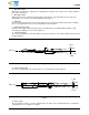
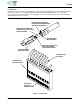
facilitate inquiries for information. Basic terms and features of this product are provided in Figure 1.
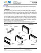
Figure 1
Locking Clip
0.64-mm [.025-in.] Square
Contacts and Housings
Locking Clip o.64-mm [.025-in.]
Square Contact
Stabilizer
Double-Row Housing,
Right End Open
Wrap-Around
Insulation Barrel
Key
Contact
Spring
Keyway
Contact
Cavity
Locking
Lance
Cavity Rib
Extraction
Slot
Extraction
Slot
Single-Row Housing,
Both Ends Closed
Double-Row Housing,
Both Ends Closed
Double-Row Housing,
Left End Open