Instruction Sheet Instruction Sheet ERGOCRIMP ERGOCRIMP Matrize Die PN 539 747-2 P/N 539 747-2 411-18211 / Rev.
Matrize PN 539 747-2 411-18211 / Rev. B1 1 Die Set PN 539 747-2 411-18211 / Rev. B1 Hinweise zum Inhalt dieser Betriebsanleitung 1 Notes to the Contens of this Manual Diese Betriebsanleitung beschreibt die Anwendung und Bedienung der ERGOCRIMP Matrize PN 539 747-2 für den Einsatz in der ERGOCRIMP Basis Handzange PN 539 635-1 sowie erforderliche Wartungsmaßnahmen.
Matrize PN 539 747-2 411-18211 / Rev. B1 2 Die Set PN 539 747-2 411-18211 / Rev.
Matrize PN 539 747-2 411-18211 / Rev. B1 3 Die Set PN 539 747-2 411-18211 / Rev.
Matrize PN 539 747-2 411-18211 / Rev. B1 Die Set PN 539 747-2 411-18211 / Rev. B1 5. Drücken Sie die Zangengriffe langsam zusammen, so daß die Matrizen aneinandergefügt und ausgerichtet werden. Drücken Sie die Zangengriffe bis zum fünften (5.) 'Klick' zusammen und ziehen Sie dann die beiden Matrizen-Befestigungsschrauben fest. 5. Slowly close the tool handles, allowing the dies to mate and/or align.
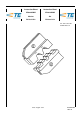
Matrize PN 539 747-2 411-18211 / Rev. B1 Die Set PN 539 747-2 411-18211 / Rev. B1 3. Positionieren Sie den Kontakt so, daß sich der Kontaktierbereich des Kontaktes auf der Seite des Kontaktpositionierers befindet und die Crimpflanken (U-Form) des Draht- und Drahtcrimps nach oben gerichtet sind. 3. Position the contact so that the mating end of the contact is on the Locator side of the tool, and that the open "U" of the wire barrels face the top of the tool.
Matrize PN 539 747-2 411-18211 / Rev. B1 Die Set PN 539 747-2 411-18211 / Rev. B1 Die Spitze muß mittig auf der Drahtcrimphülse gegenüber der Crimpnaht positioniert werden Position point on center of wire barrel opposite seam Modifizierter Amboß Modified anvil Leitungsgröße (Max.) Wire size (max.) Crimpbereich (Drahtgr.ber.markg. Crimp section (Wire size marking) Crimphöhe (A) u. Toleranz (+/- 0,05) Crimp height dim. (A) and tolerance (+/-0.
Matrize PN 539 747-2 411-18211 / Rev. B1 Die Set PN 539 747-2 411-18211 / Rev. B1 6 Einstellung der Crimphöhe 6 Crimp height adjustment Die Crimp-Handzange besitzt einen Ratschenmechanismus mit einem Einstellrad, das einen bestimmten Einstellbereich aufweist. Durch den Ratschenmechanismus wird sichergestellt, daß der Crimpzyklus vollständig beendet wird. Über das Einstellrad wird der Betätigungsweg (vor Öffnen der Ratsche) und damit die erforderliche Crimpkraft eingestellt.
Matrize PN 539 747-2 411-18211 / Rev. B1 Die Set PN 539 747-2 411-18211 / Rev. B1 7 Wartung, Instandhaltung 7 Maintenance / Inspection 7.1 Tägliche Wartung 7.1 Zur täglichen Wartung sind folgende Schritte durchzuführen: Tyco recommends that operators of the tool be made aware of the following steps of daily maintenance: 1. Entfernen Sie vom Werkzeug Staub, Feuchtigkeit und andere Rückstände mit einer sauberen, weichen Bürste oder einem fusselfreien Tuch.
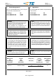
Matrize PN 539 747-2 411-18211 / Rev. B1 Die Set PN 539 747-2 411-18211 / Rev. B1 5. Crimpen Sie die Kontakte und messen Sie die Crimphöhe. Prüfkriterium für eine richtige Funktion der Handzange sind die Crimphöhenangaben aus der Tabelle (Bild 4) 5. Crimp the contacts and measure you the crimping height.
Americas Argentina - Buenos Aires Phone: +54-1-733-2000 Fax: +54-1-717-0988 Chile - Santiago Phone: +56-2-739-1230 Fax: +56-2-739-1227 Brazil - Sao Paulo Phone: +55-11-3611-1311 Fax: +55-11-3611-0397 Colombia - Bogota Phone: +57-1-231-9398 Fax: +57-1-240-3769 Canada - Toronto Phone: +905-475-6222 Fax: +905-474-5520 Mexico - Mexico City Phone: +52-5-729-0400 Fax: +52-5-361-8545 Asia/Pacific Australia - Sydney Phone: +61-2-9840-8200 Fax: +61-2-9899-5649 Fax: +81-44-844-8733 Korea - Seoul Phone: +82-2-3