
User manual


Application Specification 114-106078
Jul 11
th
, 2013 Rev. C1
This specification is a controlled document. Page 5 of 12
© Copyright 2012 by TE Connectivity Corporation
All rights reserved
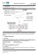
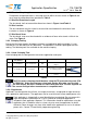
Table 1
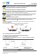
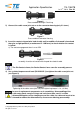
2) Crimping Contacts
Making the crimping contacts connection with suitable cross-section tooling and crimped
according to the instructions packaged with the tooling. See section 3.2.3, Crimping Tooling, of
this document for detail on tooling options.
The applied crimping dimension (within the functional range of the product) is
depended on the crimping tooling being used. Refer to the documentation
supplied with the crimping tooling for the applied crimping height.
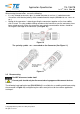
A. Wire barrel Crimp
The crimp applied to the wire barrel of the contacts is the most of compressed area and is
most critical in ensuring optimum electrical and mechanical performance of the crimped
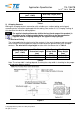
contacts. The wire barrel crimp height must be within the dimension in Table 2.
Nominal Wire Size
(mm
2
/ AWG)
Wire-End
Protrusion Length
(mm)
Wire Barrel
Crimp Width
(mm)
Wire Barrel
Crimp Height
(mm)
4.0 / 12
1.0±1.0
3.94±0.05
2.14±0.05
6.0 / 10
1.0±1.0
3.94±0.05
2.49±0.05
Table 2
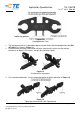
Note: The crimp width is tooling depend. Checking the crimp width is checking for the proper
tool and not a process control
Figure 4
Nominal Wire Size
(mm
2
/ AWG)
Wire Strip Length (mm)
4.0 / 12
6.5
+1.0
/-0.5
6.0 / 10
6.5
+1.0
/-0.5