
User manual


Application Specification 114-106078
Jul 11
th
, 2013 Rev. C1
This specification is a controlled document. Page 7 of 12
© Copyright 2012 by TE Connectivity Corporation
All rights reserved
3.3 Assembly of Connectors
3.3.1 Selection of Sealing & Pinch Ring for Connectors
The connector should select a suitable sealing & pinch ring for assembly according to the outside
diameter of the cable.
Pinch Ring selection criterion: Suppose the general tolerance is ±0.2mm max. of
cable Outside Diameter (OD), if norminal OD of cable is less than or equal 6.0mm,
1740379-2 is preferred, if norminal OD of cable is bigger than 6.0mm, 1987981-2
is preferred.
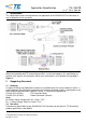
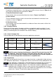
Cable Outside Diameter
Pinch Ring Type
Picture
From 5.8 up to 8.0mm
1987981-2
From 5.1 up to 6.2mm
1740379-2
Table 4
Use only PV1-F wire according to PfG 2 1169 / 08.07 or 2 PfG
1990 / 5.12 (TUV) or PV wire type ZKLA according to UL 4703 or USE-2 cable
according to UL854.
The used wire size (mm²/AWG) and the cable outer diameter must be according
to the information provided in the Tabel 2 and Table 4.
3.3.2 Assembly of the connectors
The assembly of the connectors must be performed in the following sequence:
Point 1-2 do not apply for prefabricated connector in this case the contact
crimped wire lead of cable has to be inserted directly into the correct
preassembled connector housing
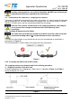
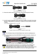
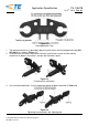
1) The engagement of the Sealing & Pinch Ring into the connector housing until it stop
(see Figure 5 and 6)
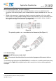
Figure 5
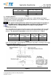
Connector Housing Components