
User manual


Application Specification 114-106078
Jul 11
th
, 2013 Rev. C1
This specification is a controlled document. Page 8 of 12
© Copyright 2012 by TE Connectivity Corporation
All rights reserved
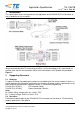
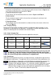
Figure 6
Preassembled Sealing & Pinch ring
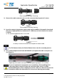
2) Connect the cable screw joint nut on to the connector housing (only 2-3 turns).
Figure 7
Preassembled Connector Housing
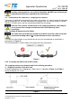
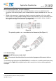
3) Insert the contact crimped wire lead of cable until an audible click sound is heard and
then give a slight pull back (a maximum of 5~10N force) to check whether the contact
is locked.
a) The contact engagement force is max.25N
Figure 8
assembly: Insertion of contact with crimped wire lead of cable
The Pin Contact shown, the Socket Contact have same the assembly process
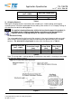
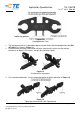
4) Use a slotted torque wrench head (PN 2232097-1) to tighten the cable screw joint nut
(see Figure 9)
Figure 9
Tightening of the cable screw joint nut (initial tightening torque is 1.8±0.1Nm)
In case of replacement components or of assembling / disassembling of the
cable entry gland, new pinch rings and seals have to be used. If a visible
deformation appears at the clamping area of the cable, the cable end needs to be
trimmed to remove the deformed area, also use new housing preassembly.