
User Manual


114- 13120
Rev E 15 of 17
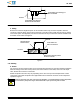
A
(Bottom of Cutout in Bezel
to Top of PC Board)
2.9+0.9
(Distance Between Bezel and Front of PC Board)
PC Board
Bezel
Cutout
Cage
Assembly
Cage Assembly Panel Grounding
Feature Compressed By Bezel
Cage Assembly
Module Locking
Latch Slightly Raised
Front View Side V iew
10 (Ref)
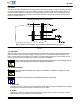
Note: Single Port Cage Assembly Shown—Requirements Also Apply to Ganged Cage Assemblies Without Light Pipe
Requirements Do Not Apply to Cage Assemblies with Light Pipe
Connector
Non--PCI
Application
PCI Application
A
(Bottom of Cutout in Bezel
to Top of PC Board)
3.5+0.3 (Distance Between Back of PC Board
Cutout and Bezel)
PC Board
Bezel
Cutout
Cage
Assembly
Cage Assembly Panel Grounding
Feature Compressed By Bezel
Cage Assembly
Module Locking
Latch Slightly Raised
Front View Side V iew
10.8 (Ref)
Connector
1_
1.02+0.3 (Distance Between Front of PC Board
Cutout to Bezel)
CAGE ASSEMBLY
(Without Light Pipe)
DIMENSION A +0.1
Single Port 0.40
Ganged 0.15
Figure 12
5. TOOLING
No tooling is required for manual placement of the connector onto the pc board. For placement of the single
port cage assembly onto the pc board, flat rock tooling can be used; extreme caution must be taken not to
touch or damage the panel grounding feature during seating. Tooling is available for seating and removing a
ganged cage assembly.
For automatic machine placement of the connector, the robotic equipment must have a true position accuracy
tolerance sufficient to properly locate the connector. This includes gripper and fixture tolerances as well as
equipment repeatability. It must use the connector datum surfaces to ensure reliable placement.
Tooling part numbers and instructional material packaged with the tooling are given in Figure 13.
5.1. Seating Tool Kit
The seating tool kit (consists of a seating tool and wall support) is used to seat a ganged cage assembly onto
the pc board. The seating tool and wall support are also available separately.
5.2. Extraction Tool
The cage assembly extraction tool is used to remove a ganged cage assembly from the pc board by pushing
the compliant pin contacts and EMI suppression pins out of their holes without overstressing the contacts.