Customer Manual TERMI-POINT* Tools 409-2002 69526-2 and 654182-1 13 MAR 08 Rev E SAFETY PRECAUTIONS 1. INTRODUCTION READ THIS FIRST ! . . . . . . . . . . . . . . . . . . . . . . . . . . 2 . . . . . . . . . . . . . . . . . . . . . . . . . . . . . . . . . . . . . . . . . . . . . . . . . . . . 3 2. PRODUCT-TO-TOOLING CROSS-REFERENCE . . . . . . . . . . . . . . . . . . . . . . . . . . . . 5 3. OPERATING INSTRUCTIONS 3.1. Pre-Operation Check . . . . . . . . . . . . . . . . . . . . . . . . . . . . . .
409-2002 TERMI-POINT Tools 69526-2 and 654182-1 DANGER SAFETY PRECAUTIONS AVOID INJURY Safeguards are designed into this application equipment to protect operators and maintenance personnel from most hazards during equipment operation. However, certain safety precautions must be taken by the operator and repair personnel to avoid personal injury, as well as damage to the equipment. For best results, application equipment must be operated in a dry, dust–free environment.
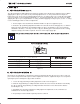
409-2002 TERMI-POINT Tools 69526-2 and 654182-1 PROPER USE GUIDELINES Cumulative Trauma Disorders can result from the prolonged use of manually powered hand tools. Hand tools are intended for occasional use and low volume applications. A wide selection of powered application equipment for extended-use, production operations is available.
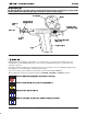
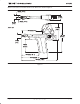
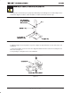
09-2002 TERMI-POINT Tools 69526-2 and 654182-1 When received, the tool should conform to the dimensions shown in Figure 2. 12.7 mm [.50 in.] 25.4 mm ÕÕ ŠŠ ŠŠ 17.5 mm [.69 in.] 28.4 mm [1.12 in.] [1.0 in.] Front of Tool 92.07 mm [3.62 in.] 133.3 mm [5.25 in.] ÒÒ ÒÒ 168.1 mm [6.62 in.] 25.4 mm [1.0 in.] 82.5 mm [3.25 in.] 104.8 mm [4.125 in.] 158.8 mm [6.25 in.] 193.5 mm [ 7.62 in.
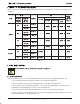
409-2002 TERMI-POINT Tools 69526-2 and 654182-1 2. PRODUCT-TO-TOOLING CROSS-REFERENCE These tools use the interchangeable mandrels listed in Figure 3. For product–to–tooling cross–reference, refer to Figure 3. WIRE CLIP COLOR TOOL 69526-2 SIZE (AWG) INSULATION SOLID OR DIAMETER Reel of 1000 RANGE (7 Strands) (mm [in.]) 22 0.99-1.14 [.039-.045] 0-69551-8 1.14-1.65 [.045-.065] 1-69411-4 0.84-1.14 [.033-.045] 0-69551-9 1.14-1.65 [.045-.065] 1-69411-3 0.71-1.14 [.028-.045] 0-69551-6 1.
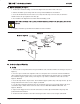
409-2002 TERMI-POINT Tools 69526-2 and 654182-1 3.2. Mandrel Installation (See Figure 4) 1. Remove the mandrel holding screw and the alignment foot from the front of the tool. 2. Pull the insulation ejector away from the tool to permit installation of the mandrel. 3. Insert the mandrel into the front of the tool so that, when the clips are in the tool, the tail of the mandrel enters the open portion of the first clip. 4. Re–install the the alignment foot and the mandrel holding screw.
409-2002 TERMI-POINT Tools 69526-2 and 654182-1 Detail A Reel Bracket Reel Insulation Support (Strain Relief) of Clip Clip Train Front of Tool Clip Feed Slot Cap Drive Block Holding Screw Ram Rod Loader Note: DO NOT force the clips. Ram Rod Loader Push to Reset Clip Feed Mechanism Front of Tool Insert Tip and Advance Clip onto Mandrel Detail B Insulation Support (Strain Relief) of Clip Clip Feed Slot Back of Tool Ram Rod Loader (In Storage Location) Figure 5 B. Unloading 1.
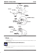
409-2002 TERMI-POINT Tools 69526-2 and 654182-1 3.4. General Operating Procedure 1. Insert an unstripped wire into the hole in the top of the mandrel. Make sure the wire bottoms in the mandrel. See Figure 6. Wire Wire Bottomed Mandrel Mandrel Figure 6 2. Slowly squeeze the trigger until it bottoms against the handle, then release the trigger. The clip is now ready to be applied to the post. 3. Hold the tool perpendicular to the panel, and slip the exposed clip over the end of the post. See Figure 7.
409-2002 TERMI-POINT Tools 69526-2 and 654182-1 CAUTION DO NOT attempt to terminate a post that has been previously terminated. ! 5. Remove the tool from the post. A properly terminated post should appear as shown in Figure 8. Be certain that stripped conductor, not the insulation, is visible at the back end of the clip. Stripped Conductor (Insulation Should Not Post Be Visible Here) Back End of Clip Insulation Support (Strain Relief) of Clip Front End of Clip Figure 8 6.
409-2002 TERMI-POINT Tools 69526-2 and 654182-1 4. ADJUSTMENTS 4.1. Clip Positioning Adjustment (Figure 10) The clip positioning assembly adjustment controls the position of the clip when it is applied to the post. When applying three clips to a post, first set the positioning adjustment to “3”. This positions the first clip at the bottom of the post. Then set the positioning adjustment to the “2” setting to place the second clip in the middle of the post.
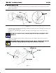
409-2002 TERMI-POINT Tools 69526-2 and 654182-1 Clip Positioning Adjustment Thumbscrew Clip Must Not Bottom on Panel or Chamfer of Post ÒÒ ÒÒ (Clearance Equal to Wire Insulation Diameter) Back of Tool Clip Positioning Assembly Adjustment Screws Figure 11 4.3. Insulation Stripping Adjustment Each tool has an adjustment (shown in Figure 1) to control the stripping action provided when the push rod forces the clip over the mandrel. These tools are set at the factory and should not require adjustment.
409-2002 TERMI-POINT Tools 69526-2 and 654182-1 Push Rod Front of Clip (Fully Extended) A Distance Between Clip and Mandrel Front of Mandrel TOOL DIMENSION A (mm [in.]) 69526-2 1.5-2.3 [.060-.090] 654182-1 2.7-3.5 [.105-.140] Figure 12 Adjust the push rod as follows: 1. Remove the loading tool, break the clip train strip as it enters the back of the tool, and remove the reel bracket. 2. Loosen the clip positioning assembly adjustment screw behind the clip positioning adjustment thumbscrew.
409-2002 TERMI-POINT Tools 69526-2 and 654182-1 5. PREVENTIVE MAINTENANCE AND INSPECTION 5.1. Lubrication A periodic lubrication schedule, using any good grade SAE 20 motor oil, should be maintained at the intervals specified in Figure 13. 1. Squeeze the tool handles to expose the push rod. 2. Apply a light coat of lubricant to the top of the push rod. CAUTION DO NOT allow the lubricant to contact the clips or clip contact surfaces (such as the mandrel). ! 3.
409-2002 TERMI-POINT Tools 69526-2 and 654182-1 5.2. Inspection The following items should be checked periodically to ensure proper operating efficiency of the tooling. 1. Be certain the screws (Figure 17, Items 14, 15, 20, and 21) are tight. 2. Clean the tool and remove insulation scraps on a regular basis. 3. When the tool is cycled to apply clips, observe the operation of the tool. If binding of moving parts is noted, lubricate the tool as described in Paragraph 5.1. 4.
409-2002 TERMI-POINT Tools 69526-2 and 654182-1 6. TROUBLESHOOTING Every tool is thoroughly inspected before leaving the factory and should be in perfect operating condition when it reaches the customer. If, at anytime, the tool does not function properly, refer to Figure 16. SYMPTOM Clips do not feed from the tool. POSSIBLE CAUSE REMEDY Clips are not properly seated in the tool. Refer to Paragraph 3.3.,A., Loading. Incorrect clip or mandrel is being used.
409-2002 TERMI-POINT Tools 69526-2 and 654182-1 7. REPLACEMENT AND REPAIR Customer–replaceable parts are listed in Figure 17. A complete inventory should be stocked and controlled to prevent lost time when replacement of parts is necessary. Parts other than those listed should be replaced by Tyco Electronics to ensure quality and reliability.
409-2002 TERMI-POINT Tools 69526-2 and 654182-1 PART NUMBER ITEM QTY PER DESCRIPTION 69526-2 654182-1 (Detail A) (Detail B) ! '(3 ! +)*3 '5'1 $3%* +)*3 '(3 +)*3 '(3 # -+&+.
409-2002 TERMI-POINT Tools 69526-2 and 654182-1 Detail A Ċ Tool 69526-2 17 25 21 4 1 24 10 5 37 19 18 9 15 22 24 20 14 10 8 14 26 10 13 23 43 16 36 35 27 30 33 31 27 29 32 3 28 34 Opening of roll pin must 11 12 be positioned as shown.
409-2002 TERMI-POINT Tools 69526-2 and 654182-1 Detail B Ċ Tool 654182-1 17 38 24 25 7 42 41 4 6 37 22 9 15 8 41 39 42 24 40 10 14 10 14 26 13 43 23 16 36 35 29 33 31 27 2 27 3 30 32 28 34 Opening of roll pin must 11 12 be positioned as shown.
409-2002 TERMI-POINT Tools 69526-2 and 654182-1 7.1. Mandrel Replacement If a mandrel becomes broken or worn, it will be necessary to replace the mandrel to insure proper clip application. Refer to Figure 3 to select the appropriate mandrel. 7.2. Push Rod Replacement If clips do not feed from the tool, the push rod may be broken or bent. Refer to 17, Item 2 for the push rod assembly part number. The push rod can be replaced without completely dismantling the tool.
409-2002 TERMI-POINT Tools 69526-2 and 654182-1 Detail A Side Plates Detail B Flange on Push Rod Push Rod Plate Drive Block Hooks on Push Rod Plate Must Engage Left and Right Side Plates Push Rod Plate Back of Tool Detail D Back of Tool Push Rod Groove Push Rod Trigger Bottomed Against Handle Detail C Flanges on Push Rod Engage the Notches on Drive Block Push Rod Plate Figure 19 8.