
Datasheet


1
03-2014, Rev. 0314
www.te.com
© 2014 Tyco Electronics Corporation,
a TE Connectivity Ltd. company.
Datasheets and product specification ac-
cording to IEC 61810-1 and to be used only
together with the ‘Definitions’ section.
Datasheets and product data is subject to the
terms of the disclaimer and all chapters of
the ‘Definitions’ section, available at
http://relays.te.com/definitions
Datasheets, product data, ‘Definitions’ sec-
tion, application notes and all specifications
are subject to change.
Contact Data
Contact arrangement 1 form A, 1 NO/1 NO (2x87) 1 form U, 2 NO 1 form C, 1 CO
Contact gap >0.8mm
Rated voltage 12VDC 24VDC 12VDC 24VDC 12VDC 24VDC 24VDC
1)
Limiting continuous current NO NO NO NO NO/NC NO/NC NO/NC
23°C 60A 60A 2x32A 2x32A 60/45A 60/45A 60/45A
85°C 40A 40A 2x25A 2x25A 40/30A 40/30A 40/30A
125°C 17A 17A 2x11A 2x11A 17/12A 17/12A 17/12A
Limiting making current
2)
NO/NC 120A 120A 2x100A 2x100A 120/45A 120/45A 120/45A
Limiting breaking current
NO/NC 60A 20A 2x40A 2x15A 60/40A 20/15A 30/20A
Limiting short-time current
overload current, ISO 8820-3
3)
:
1.35 x 40A, 1800s 1.35 x 40A, 1800s 1.35 x 40A, 1800s
2.00 x 40A, 5s 2.00 x 40A, 5s 2.00 x 40A, 5s
3.50 x 40A, 0.5s 3.50 x 40A, 0.5s 3.50 x 40A, 0.5s
6.00 x 40A, 0.1s 6.00 x 40A, 0.1s 6.00 x 40A, 0.1s
Jump start test
ISO 16750-1 24VDC for 5min conducting nominal current at 23°C
Contact material silver based
Min. recommended contact load
4)
1A at 5VDC
Initial voltage drop
NO contact at 10A, typ./max. 15/200mV 15/200mV 2x15/200mV 2x15/200mV 15/200mV 15/200mV 15/200mV
NC contact at 10A, typ./max. 20/250mV 20/250mV 20/250mV
Frequency of operation
at nominal load 6 ops./min (0.1Hz)
Operate/release time typ. 7/2ms
5)
Electrical endurance
resistive load at 14VDC >2x10
5
ops. >2x10
5
ops. >2x10
5
ops.
40A 2x25A 40A (NO)
resistive load at 28VDC >1x10
5
ops. >1x10
5
ops. >1x10
5
ops. 1x10
5
ops.
20A 2x15A 20A (NO) 30A (NO)
>5x10
5
ops.
10A (NC)
Mechanical endurance
DC coil >1x10
7
ops.
1) Special high performance 24VDC version with contact gap >0.8mm.
2) The values apply to a resistive or inductive load with suitable spark suppression and at maximum 14VDC for 12VDC or 28VDC for 24VDC load voltages. For a load current duration of
maximum 3s for a make/break ratio of 1:10.
3) Current and time are compatible with circuit protection by a typical automotive fuse. Relay will make, carry and break the specified current.
4) See chapter Diagnostics of Relays in our Application Notes or consult the internet at http://relays.te.com/appnotes/
5) For unsuppressed relay coil. A low resistive suppression device in parallel to the relay coil increases the release time and reduces the lifetime caused by increased erosion and/or higher
risk of contact tack welding.
Power Relay F4
Automotive Relays
Plug-in Mini ISO Relays
n
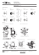
Pin assignment similar to ISO 7588 part 1
n
Plug-in or PCB terminals
n
Also available for 42VDC applications
Customized versions on request
– 24VDC versions with contact gap >0.8mm
– Integrated components (e.g. resistor, diode)
– Customized marking/color
– Special covers (e.g. notches, release features, brackets)
– Various contact arrangements and materials
– For latching (bistable) version refer to Power Relay F7 A Latching
or Mini Relay Latching
– For shrouded/weatherproof dust cover versions refer to
Shrouded Power Relay F4 A and VF4 A
Typical applications
Cross carline up to 40A for example: ABS control, blower fans, car alarm,
cooling fan, Electric Power Steering, energy management, engine control,
fuel pump, heated front screen, lamps: front, rear, fog light, main switch/
supply relay, valves, wiper control.
F134co_fcw1