
Brochure


AMP Circular Connectors for
Commercial Signal and Power Applications
6
Catalog 82021 Dimensions are in inches and Dimensions are shown for USA: 1-800-522-6752 South America: 55-11-2103-6000
Revised 7-07 millimeters unless otherwise reference purposes only. Canada: 1-905-470-4425 Hong Kong: 852-2735-1628
specified. Values in brackets Specifications subject Mexico: 52-55-1106-0800 Japan: 81-44-844-8013
www.tycoelectronics.com are metric equivalents. to change. C. America: 57-1-254-4444 UK: 44-208-420-8341
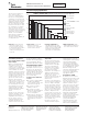
Performance Characteristics — CPC and Metal-Shell CPC Connectors
Note: All part numbers
are RoHS Compliant.
More information on the
performance of AMP CPC
and metal-shell CPC
connectors is available by
requesting the following
AMP Product Specifications:
108-10024––
CPC Connectors
108-10037––
Type XII Contacts
108-10020––
Size 20 DM and 20 DF
Contacts
108-10040––
Metal-Shell CPC
Connectors
108-10042––
Type III+ Contacts
108-1579––
Sealed CPC Connectors
with Removeable Contacts
Test Description Procedure Requirements
Maintenance Contacts removed and No damage to contacts
Aging reinserted 10 times using or housings. Contact
applicable tools retention maintained
Contact Retention Axial load applied to Contacts remain in
contact to displace to the place when subjected to
rear of the connector a minimum 10 lb. load*
Dielectric Withstanding Connectors subjected to No breakdown or
Voltage (MIL-STD-1344, 1500 volts rms at sea flashover
Method 3001) level
Thermal Shock Connectors subjected to No damage
five cycles of temperature
change (-55°C and +125°C)
Vibration Connectors vibrated No damage or loosening of
(MIL-STD-202, (wired and mated). parts. No interruption
Method 204, Contacts wired in series of electrical continuity
Test Condition B) with 100 milliamperes longer than 10 microseconds
flowing during the test
Physical Shock Connectors shocked No damage or loosening
(MIL-STD-202, 50 G (wired and mated). of parts. No interruption of
Method 213A, Contacts wired in series electrical continuity longer
Test Condition A) with 100 milliamperes than 10 microseconds
flowing during the test
Durability Connectors mated and No wear through
unmated 25 times with tin damage to plating
plated contacts and 500
times with gold plated
contacts
Corrosion (Salt Spray) Mated connectors No damage
(MIL-STD-202, Method 101, subjected to 5% salt
Test Condition B) spray for 48 hours
Protection Against a. Test wire is pushed a. Must not touch live parts
Solids into mated connectors b. No dust deposits
b. Mated connectors observed on mating
subjected to circulating surfaces
talcum powder
Protection Against Water is projected through No water deposits shall
Water jets against mated be observed on mating
connector from any direction surfaces of contacts
and then temporarily or housings
immersed in water
Temperature Life Mated connectors No damage
subjected to a temperature
of +125°C for 200 hours
Insulation Resistance Measurement made 5000 megohms
(MIL-STD-1344, between adjacent contacts minimum ambient
Method 3003) with connector mated temperature
Humidity Mated connectors Minimum insulation
(MIL-STD-202, Method 103, subjected to 10 days resistance of
Test Condition B) moisture test 100 megohms
*For size 16 contacts. Size 8 contacts 25 lb. load, min.