
Datasheet


Mini- Universal MATE- N- LOK Splash- Proof Sealed Connectors
114- 13089
Rev B 7 of 20Tyco Electronics Corporation
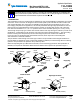
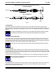
Wire Barrel Closed with No
Wire Strands Showing in Seam
FlushWithorExtendfromEndofWireBarrel
to 0.89 [.035] (Max) Wire Conductor Location
0.00--0.25 [.000--.010]
Front Bellmouth
0.10--0.51 [.004--.020]
Rear Bellmouth
X
1.63--1.93 [.064--.076]
Effective Crimp Length
0.25 [.010]
Max Flash
Section X- X
(Wire Barrel)
Crimp Height
(See Table)
Crimp Width
(See Table)
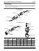
0.13 [.005] Max
Burr
0.38 [.015] Max
Cutoff Tab
0.51--0.71 [.020--.028]
Locking Lance Position
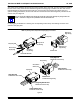
Transition Area (Wire Conductors
Must Be Visible Here, Wire Insulation
May Be Visible Here)
0.4 [.015] Min
Wire Seal Protrudes into Transition Area
8_ Max Tilt of Wire Seal
Wire Strands Do Not Extend
Beyond Height of Wire Barrel
No Flash
Section Y- Y
(Insulation Barrel)
“F” Crimp
Crimp Width
(See Table)
Figure 5 (cont’d)
Y
Y
X
Tips of Insulation Barrel
Turn Inward
Note: Socket Contact Shown, Requirements Apply Equally to Pin Contact