
User Manual
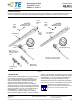

Table Of Contents
- 1. INTRODUCTION
- This instruction sheet describes the use of Extraction/ Lance Reset Tools 843477-[ ] and 843996-2, -3, -4, and -5. These tools are designed to remove MTE*, Mod IV, Tandem Spring, and Mini Tandem Spring contacts from housings and reset the overly depr...
- Read these instructions thoroughly before attempting to remove any contacts or resetting the locking lances.
- Reasons for revision of this document can be found in Section 6, REVISION SUMMARY.
- 2. DESCRIPTION
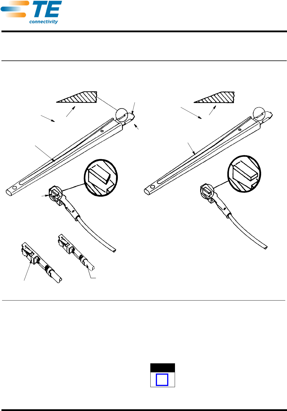
- Each tool features a handle marked with the specific part number, a contact lance release tip, a locking lance reset portion, and a tool stop. The contact lance release tip depresses the contact locking lance to allow extraction of the contact. The t...
- Generally, all tools except tools 843477-5 and 843996- 5 can be classified as top release tools in that - during the extraction process - they are inserted into the top of the housing to depress the locking lance from the top, as shown in Figure 3, V...
- 3. EXTRACTION PROCEDURE
- 3.1. Extraction Tools 843477-1, -2, -3, -4 and Tools 843996-2, -3, -4 (Figure 3, View A)
- Tools represented in View A of Figure 3 release the locking lance from the top of the housing cavity as shown.
- These steps are recommended:
- 1. Orient the wide part of tip with the narrow part of locking lance cavity.
- 2. Insert tool tip into BACK of lance cavity until tool stop bottoms on housing.
- 3. Holding tool in position, grip wire and pull contact out of housing.
- 4. Remove tool from housing.
- 5. Repeat Steps 1 through 4 for AMPMODU MTE housings when contact reaches preload window (see Figure 2).
- 3.2. Extraction Tools 843477-5 and 843996-5 (Figure 3, View B)
- Tools 843477-5 and 843996-5 release the locking lance from the side of the housing cavity.
- Proceed as follows:
- 1. Align tool so that wide part of tip is oriented with long part of lance cavity, and tip taper is opposite locking lance.
- 2. Insert tool tip between locking lance and housing until the tool stop bottoms.
- 3. Pull back lightly on the wire and, if necessary, move tool just enough to release the lance.
- 4. Remove the contact from the housing; then remove the tool.
- 4. LOCKING LANCE RESET PROCEDURE (Figure 3, View C)
- The tools described on this sheet are designed to reposition depressed locking lances to ensure retention in the housing. Check compatibility of the contact and tool; then proceed as follows:
- 1. Orient the reset tip so the taper is facing the locking lance.
- 2. Keep the reset tip flat against the receptacle box and slide it toward the base of the locking lance until it bottoms.
- 3. Remove tool tip and contact will be ready for re- insertion into the housing.
- 5. TOOL INSPECTION/MAINTENANCE
- 6. REVISION SUMMARY
©2011 Tyco Electronics Corporation, a TE Connectivity Ltd. Company
All Rights Reserved
*Trademark
TE Connectivity, TE connectivity (logo), and TE (logo) are trademarks. Other logos, product and/or Company names may be trademarks of their respective owners.
1 of 4
Instruction Sheet
TOOLING ASSISTANCE CENTER
1-800-722-1111
PRODUCT INFORMATION
1-800-522-6752
This controlled document is subject to change.
For latest revision and Regional Customer Service,
visit our website at www.te.com
LOC B
Extraction/Lance Reset
Tools 843477-[ ], and
843996-2, -3, -4, and -5
408-9453
19 APR 11 Rev E
PROPER USE GUIDELINES
Cumulative Trauma Disorders can result from the prolonged use of manually powered hand tools. Hand tools are intended for occasional use
and low volume applications. A wide selection of powered application equipment for extended-use, production operations is available.
Figure 1
1. INTRODUCTION
This instruction sheet describes the use of Extraction/
Lance Reset Tools 843477-[ ] and 843996-2, -3, -4,
and -5. These tools are designed to remove MTE*,
Mod IV, Tandem Spring, and Mini Tandem Spring
contacts from housings and reset the overly
depressed contact locking lances of the removed
contact (see Figure 1). The two tool types are basically
the same except for the lance reset angles. The reset
angle of tool 843477-[ ] is 21° and the reset angle of
tool 843996-2, -3, -4, and -5 is 17°. This is to
accommodate the different designs of the locking
lances of Mod IV, Mod IV.v, Mod V contacts, as shown
in Figure 1 and Figure 2. The 843477-[ ] tools are used
with contacts having the old style locking lance design
and 843996-2, -3, -4, and -5 tools are used with the
contacts with the new style locking lance design.
Read these instructions thoroughly before attempting
to remove any contacts or resetting the locking lances.
All dimensions are in millimeters [followed by
inches in brackets]. Figures and illustrations are for
reference only and are not drawn to scale.
Lance
Reset
Angle
Tool 843477-[ ]
Locking
Lance
21°
Lance
Release
Tip
Lance
Reset
Angle
17°
Mod IV, IV.v, or
Mod V Contact with
Old-Style Locking
Lance
Mini Tandem
Spring Contact
Tapered Tip
Mod IV, IV.v, or Mod V Contact
with New-Style Locking Lance
Tandem Spring
Contact
Flat (Nontapered) Tip
Lance
Reset
Portion
Tool 843996-2, -
3,-4, and -5
NOTE
i