
Datasheet


Seite / Page 9 of 14 ECOC: EGC0 ; LOC: AI
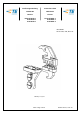
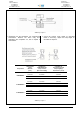
Matrize
PN 9-1579022-1
9-1579022-2
9-1579022-3
411-18465 / Rev. A1
Hand Tool
PN 9-1579022-1
9-1579022-2
9-1579022-3
411-18465 / Rev. A1
5 Crimpverfahren
HINWEIS
Die CERTILOK Handzange bietet eine Einstell-
möglichkeit der Crimphöhe. Die Crimphöhe
(Kap. 5 und 6, bzw. Abbildung 7) muss zum
Anfang, wie nachfolgend beschrieben, überprüft
werden bevor gewünschte Kontakte und
Leitungsgrößen verarbeitet werden.
Wählen Sie eine Leitung mit spezifizierter Größe und
Isolationsdurchmesser (Abbildung 3). Entfernen Sie
die Leitungsisolation um die angegebene Länge ohne
die Drahtlitzen zu beschädigen. Wählen Sie einen
passenden Kontakt und bestimmen Sie die korrekte
Kontaktaufnahme der Matrize entsprechend der
Markierungen (Leitungsgröße). Verfahren Sie nun wie
folgt:
1. Drücken Sie die Zangengriffe zusammen und
lassen Sie die Zange vollständig öffnen.
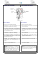
2. Halten Sie die Crimpzange so, dass die Leitungs-
seite zu Ihnen zeigt. Halten Sie den zu crimpenden
Kontakt fest und schieben Sie ihn in die Zange.
3. Positionieren Sie den Kontakt so in den Kontaktpo-
sitionierer, dass die U-Form des Isolations- und
Drahtcrimps nach oben gerichtet sind.
VORSICHT
Stellen Sie sicher, dass die Crimpflanken des
Isolations- und Drahtcrimp des Kontaktes
gleichmäßig geführt werden. Versuchen Sie
NICHT einen ungenau positionierten Kontakt zu
crimpen.
4. Halten Sie den Kontakt in Position und drücken Sie
die Zangengriffe soweit zusammen, bis der
Ratschenmechanismus entsprechend verriegelt
und der Kontakt in der Zange gehalten wird. Achten
Sie darauf, dass Sie die Isolations- und Drahtcrimp-
flanken NICHT deformieren.
5. Führen Sie die abisolierte Leitung in die
Drahtcrimphülse (Abbildung 6).
6. Halten Sie die Leitung in dieser Stellung und
drücken Sie die Zangengriffe zusammen, bis der
Ratschenmechanismus auslöst bzw. öffnet. Lassen
Sie die Zange vollständig öffnen und entnehmen
Sie den gecrimpten Kontakt.
5 Crimping procedure
NOTE
The CERTILOK hand tool has been designed
with a crimp adjustment feature. Initially, the
crimp height ( chapter 5, 6 and Figure 7) should
be verified before using the tool to crimp desired
contacts and wire sizes.
Refer to the Figure 3 and select a wire of the specified
size and insulation diameter. Strip the wire to the
length indicated in Figure 3., taking care not to bend or
to damage the wire strands. Choose a fitting contact
and identify the appropriate cross section according to
the wire size marked on the die set. Proceed as
follows:
1. Squeeze tool handles together and allow them to
open fully.
2. Hold the tool so that the wire side of the tool is
facing you. Insert the contact in the tool.
3. Insert the contact in the contact locator so that the
open “U” of the insulation and wire crimp face the
top of the tool.
CAUTION
Make sure that both insulation and wire crimp of
the contact are started evenly into the crimping
station. Do NOT attempt to crimp an improperly
positioned contact.
4. Hold the contact in position and squeeze the tool
handles together until ratchet engages sufficiently
to hold the contact. Do NOT deform insulation
flanks or wire flanks.
2. Insert stripped wire into the wire barrel of the
contact (Figure 6).
3. Holding the wire in place, squeeze tool handles
together until ratchet releases. Allow tool handles
to open fully and remove contact.