14-18025 Verarbeitungsanweisung Application Specification 04 May 2015 Rev T EC: -- MQS contact system SWS Inhaltsverzeichnis Seite 1. ZWECK 3 2. ZUSÄTZLICHE UNTERLAGEN 3 2.1 Kundenzeichnungen 3 2.2 Produktspezifikation 3 2.3 Verarbeitungsspezifikationen 3 2.4 Kundenbroschüren 3 2.5 Prüfvorschrift 3 2.6 Informationsblätter 3 3. VERARBEITUNG 5 3.1 Einzeldichtung 963379 5 3.2 Einzeldichtung 967067 5 3.3 Blindstopfen 5 4. BESCHREIBUNG 7 5.ANFORDERUNGEN 9 5.
114-18025 Table of Contents Page 1. SCOPE 4 2. REFERENCED DOCUMENTS 4 2.1 Customer Drawings 4 2.2 Product Specification 4 2.3 Application Specification 4 2.4 Information Material 4 2.5 Inspection Instructions 4 2.6 Information Sheets 4 3. APPLICATION 6 3.1 Single-Wire Seal 963379 6 3.2 Single-Wire Seal 967067 6 3.3 Dead-End Plug 6 4. DESCRIPTION 8 5. REQUIREMENTS 10 5.1 Wire 10 5.2 Cutoff and Burrs 10 5.3 Wire Crimp 10 5.
114-18025 1. ZWECK Diese Spezifikation beinhaltet die Richtlinien zur Verarbeitung von Stift- und Buchsenkontakten des MQS Kontaktsystems mit Einzeldichtung. Die Angaben gelten primär für halb- oder vollautomatische Verarbeitung, können jedoch auch nach Vereinbarung für Handcrimpwerkzeuge angewendet werden. Die Kontakte sind nach ihrer Verwendung, nach Drahtgrößenbereichen und Crimpdaten unter Punkt 6 aufgeführt.
114-18025 1. SCOPE This specification contains the guidelines for the application of pin and socket contacts of the MQS contact system with single-wire seals. It applies primarily to the fully or semi-automatic application of the contacts; if agreed, it can also be applied to manual crimp tools. The contacts are listed by their use, the wire size ranges and crimping data in section 6. Note: Only the TE crimp tools specified in section 6 may be used for application of the contacts.
114-18025 3. VERARBEITUNG 3.1 Einzeldichtung 963379 (Kammer-∅ ∅ 4mm) 1) Die Einzeldichtungen sind auf einem gelochten Metallband aufgereiht. Das Band wird von der Transportspule abgewickelt und einem Verarbeitungsautomaten, dem Scat-Modul, zugeführt. Dort werden die Einzeldichtungen aus dem Metallband entnommen, auf maximal 450% ihres Innendurchmessers mit der Verarbeitungshülse 515945-1 aufgeweitet, über der Leitung positioniert und abgestreift.
114-18025 3. APPLICATION 3.1 Single-Wire Seal 963379 (cavity ∅ 4mm) 1) The single-wire seals are arranged on a punched metal strip which is unwound from the transport reel and fed into the automatic application machine, the Scat module. Here, the single-wire seals are removed from the metal strip, extended to a maximum of 450% of their internal diameter with the application sleeve 515945-1, positioned on the wire and pushed from the sleeve.
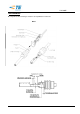
114-18025 4. BESCHREIBUNG Die aufgeführten Bezeichnungen werden in der Spezifikation verwendet.
114-18025 4. DESCRIPTION The following terms are used in the specification. Fig.
114-18025 5. ANFORDERUNGEN 5.1 Leitung A Auswahl Es dürfen nur Leitungen nach DIN 72551-FLR Teil 5 und 6, sowie FLR und FLU Leitungen nach LV112-1 verarbeitet werden, die die Bedingungen nach Tabelle 1 und 2 dieser Spezifikation erfüllen. Andere Leitungen benötigen die Freigabe der Entwicklungsabteilung. Es sind nur Einzelanschläge zugelassen. Für Leiterquerschnitte kleiner 0,22mm² in zugverstärkter Ausführung gilt zusätzlich LV 112-4.
114-18025 5. REQUIREMENTS 5.1 Wire A Selection Only wires in accordance with DIN 72551-FLR Parts 5 and 6 as well as FLR and FLU wires in accordance with LV112-1 which comply with the conditions specified in Tables 1 and 2 may be used. Other wires require approval from the development department. Only single termination is permitted. For wire size smaller than 0,22mm² (reinforced version) additionally LV 112-4 is valid.
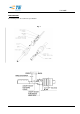
4-18025 According to Spec. 114-18022 5.4 Isolationscrimp bzw. Crimp für Einzeldichtung A Lage der Einzeldichtung auf dem Leiter Das Ende der Leiterisolation muß mindestens 0.3mm und darf max. 0.6 mm vorstehen (siehe Bild 2). Bild 2 B Crimpdaten für Einzeldichtungen Die Crimpform, Crimpbreiten und eine Empfehlung für die Crimphöhe sind in Tab. 1, die Bestell-Nummern der Einzeldichtungen in Tab. 2 aufgeführt. Die Crimphöhe ist optimal eingestellt, wenn der Crimp die Einzeldichtung möglichst rund umfaßt.
114-18025 5.4 Insulation Crimp and Crimp for Single-Wire Seal A Position of the single-wire seal on the wire The end of the wire insulation must at least be 0.3mm and may extend not more than 0.6 mm beyond the front face of the seal (see Fig. 2). Fig. 2 B Crimping data for single-wire seals The shape, width and reference value for the height of the crimp are shown in Table 1 and the Order Numbers of the single-wire seals are listed in Table 2.
114-18025 5.5 Kontaktbereich Überfeder mit Rastfeder sowie Kontaktkörper mit Kragen für Sekundärverriegelung dürfen durch den Crimpvorgang weder verbogen noch deformiert sein. 5.6 Form- und Lagetoleranzen des gecrimpten Kontaktes (siehe Bild 4) A Parallelität Der Boden des Drahtcrimps bzw. des Crimps für die Einzeldichtung muss innerhalb einer Parallelitätstoleranz von 0.25mm liegen, bezogen auf den Boden des Kontaktkörpers. B Symmetrie Der seitliche Versatz bzw.
114-18025 5.5 Contact Area After crimping, neither the cantilever spring with locking lances nor the contact body with collar for secondary retention may be bent or deformed. 5.6 Shape and Positional Tolerances of the Crimped Contact (see Fig. 4) A Parallelism The base of the wire crimp or of the crimp for the single-wire seal must be parallel to the base of the contact body within a tolerance of 0.25mm. B Symmetry The lateral offset of the crimp for the single-wire seal must lie within a tolerance of 0.
114-18025 Tabelle 1: Buchsen- und Stiftkontakte / Table 1 Socket- and pin contacts FLU Ausführung / Contact Isolations- ø LeiterAbisoDrahtcrimp / Wire crimp / Insul. querlierRange schnitt / länge / Band-ware/ Einzelware / Wire size Strip Crimp- Mess- Höhe / Form Loose piece bare Height / length profilStrip breite / CrimpShap [mm] CH1 e [mm²] ±0,15 crimper breite / [mm] profile measure ±0,03 width able *±0,02 crimp [mm] CB1 width FLR Bestellnummer / Order No.
114-18025 customer. Not for new applications! 7) reference, see capture 5.4 B 8) Conta ct-, wire combi nation has not yet been consid ered Tabelle 2: Einzeldichtungen / SINGLE-WIRE SEALS Order No: Strip Bestell-Nr.: Bandware Order No: loose piece Bestell-Nr.: Einzelteile 963379-61) 963379-71) Cavity-Ø in seal area Kammer-Ø im Dichtbereich [mm] Color Wire size Farbe LeitungsQuerschnitt For insulationØ [mm2] Für IsolationsØ [mm] FLR Scat-module 4 black / schwarz grey / grau 0.5 0.2 - 0.35 1.
114-18025 7. Montagehilfe Zur Gehäusebestückung von Kontakten mit Einzeldichtung wird im Bedarfsfall folgendes Hilfswerkzeug empfohlen: Montagehinweis: Die Zange muss so angesetzt werden, dass ein Luftspalt von ca. 1-5mm zwischen Vorderkante Zange und Ende der Dichtung ist. Durch leichtes Öffnen der Zange kann die Dichtung nachgedrückt werden. Bestell-Nr.
114-18025 7. Assembly Tool If necessary, the following assembly tool is recommended for the insertion of contacts with single-wire seals into the housings: Assembly note: the tool must be positioned so that there is an air gap of approximately 1-5mm between its front edge and the end of the seal. The seal can be pushed into position by slightly opening the tool. Order No.
114-18025 8. Blindstopfen für Kammer-∅ ∅ 3.45mm und Kammer-∅ ∅ 4mm Zur Abdichtung nicht mit Kontakten belegter Kammern stehen Blindstopfen zur Verfügung.
114-18025 8. Dead-End Plugs for Cavity ∅ 3.45mm and cavity ∅ 4mm Dead-end plugs are available for sealing cavities which are not occupied by contacts.
114-18025 T Sheet 7, 8: Fig. / Bild 1updated. Sheet 12: D corrected bunch was collar G.Abraham 08.10.2015 S Crimp tool number and hand crimp tool number corrected M.Brunner 04.05.2015 R Note for column ISO CH added. Views of the crimped contacts (below the tables) corrected Seals for FLU wires added (table 2) / Adaptation stripping length (table 1 + 2) M.Brunner 27.11.