
Datasheet

114-18025
Rev T 10
of
21
5. REQUIREMENTS
5.1 Wire
A Selection
Only wires in accordance with DIN 72551-FLR Parts 5 and 6 as well as FLR and FLU wires in accordance
with LV112-1 which comply with the conditions specified in Tables 1 and 2 may be used. Other wires
require approval from the development department. Only single termination is permitted. For wire size
smaller than 0,22mm² (reinforced version) additionally LV 112-4 is valid.
B Preparation
The wire must be stripped to the length specified in Table 1, taking care that the individual strands are
neither bent nor cut off.
For application with single-wire seals, the insulation in the seal area must be undamaged and may not be
compressed or deformed. Its surface must be free of contamination.
5.2 Cutoff and Burrs
The cutoff must be visible after crimping. Its length may not exceed 0.3 mm.
The burr at the cutoff point may not exceed 0.03 mm.
5.3 Wire Crimp
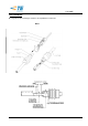
A Wire position
After crimping, the end of the wire must extend 0.1 to 0.7 mm beyond the front edge of the wire crimp. The
mating and locking function of the contact must not be affected by the over standing single wires.
At contacts used with a wire size range of 0,75mm², a conductor over standing of max. 0,4mm is allowed.
Upraising single wires are not permitted. In no case may the end of the insulation be crimped under the wire
crimp.
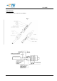
B Crimping data
The shape, height and width of the crimp, and the wire range, are shown in Table 1.
Note: measure the crimp height in accordance with operating instructions IS 7424 with a crimp height
micrometer, TE Order No. 675836-0. The crimp width is a tool-related dimension and is defined as the distance
between the two tangential points of the rolling radii and the edges of the crimp. It is not
possible to test the crimp width for production monitoring purposes.
The inspection dimension CP
1
and CP
2
are used only for checking the crimper width in the tool, not for
statistical monitoring of the crimp width or the quality of the crimp.
For wire-size <0.35mm² the following exceptions for the Evaluation of microsection are valid:
Flank End Distance R: At cables with 7 strands (reinforced version) due to stubbing of the crimp wing on a
strand a twisting may occur. In this area the crimp leg end may hit the inner wall of the crimp barrel (R=0).
C Extraction forces
The extraction forces must comply with the requirements of DIN EN 60352-2.
D Crimp bellmouth
In contrast to the general guidelines, the size of the rear bellmouth is 0.25 ± 0.15mm for all wire ranges.
A missing of the front bellmouth is permitted.
E Burr on base of crimp