TEAC AG20D 5.1 CHANNEL HOME THEATRE RECEIVER AG20D 5.1 CHANNEL HOME THEATRE RECEIVER POWER VOLUME STEREO STATION APS RESET PHONES TAPE AUX TUNER/BAND VIDEO 1 VIDEO 2 DVD DTS/ DOLBY DIGITAL 2CH DIGITAL IN SURROUND MODE SUB ON/OFF USER MANUAL IMPORTANT! WARRANTY INFORMATION INSIDE.PLEASE READ WWW.teac.com.
WARRANTY REGISTRATION Please read this warranty card. Keep your purchase receipt to enable you to proceed quickly in the event of a Warranty Service. Warranty Terms & Conditions 1. TEAC warrants to the original retail purchaser only, that this product is free from defects in material and workmanship under normal domestic use and authorises free service during the warranty period at any TEAC Authorised Service Centre only. TEAC warranty only applies to products purchased, used and serviced in Australia.
9. This warranty does not apply to equipment showing abuse, damage or that it may have been tampered with, altered or repaired outside any TEAC Authorised Service Centre. If so, the warranty will be void. *Your nearest Authorised TEAC Service Centre is listed in your Owners Manual 10. No one is authorised to assume any liability on behalf of TEAC or impose any obligation on it, in connection with the sale of any equipment other than as stated in this warranty and outlined above. 11.
WARRANTY PROCEDURES Please keep this information for your own records. Please refer to the owner’s manual to ensure that you have followed the correct installation and operating procedures. 1. 2. 3. Read owner’s manual carefully If you require Warranty Service, please contact the TEAC Authorised Service Centre Please have your purchase receipt as your proof of purchase and the following details completed for a valid Warranty. Owner’s Name Owner’s Address Postcode Model Name/No. Serial No.
CONTENTS SAFETY INFORMATION……………………………………………………………………………………………. 1 IMPORTANT SAFETY INSTRUCTIONS …………………………….…………………………………..………. 2 BEFORE USE ………………………………………………………………………………………………..……….4 CONNECTION ……………………………………………………………………………………………..………… 5 REMOTE CONTROL UNIT ………………………………………………………………………………..……….. 10 FRONT PANEL INFORMATION ……………………………………………………………………….…………... 11 REAR PANEL INFORMATION ………………………………………………………………………….………….. 12 REMOTE CONTROL INFORMATION ………………………………………………………………….………….
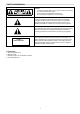
SAFETY INFORMATION Caution: To reduce the risk of electric shock, do not remove Cover (or back) No user-serviceable parts inside. Refer servicing to qualified service personnel. Do not expose this appliance to rain or moisture This lightning flash with arrowhead symbol, within an equilateral triangle is intended to alert the user to the presence of uninstalled “dangerous voltage” within the product’s enclosure that may be of sufficient magnitude to constitute a risk of electric shock to persons.
IMPORTANT SAFETY INSTRUCTIONS CAUTION: READ THIS BEFORE OPERATING YOUR UNIT. 1. READ AND FOLLOW INSTRUCTIONS: All the safety and operation instructions should be read before the product is operated. Follow all operation instructions within this manual. 2. RETAIN THESE INSTRUCTIONS: The safety and operation instructions should be retained for future reference. 3. HEED WARNINGS: Comply with all warnings on the product and in the operation instructions. 4.
IMPORTANT SAFETY INSTRUCTIONS b) c) d) e) f) If liquid has been spilled, or objects have fallen into the product. If the product has been exposed to rain or water. If the product does not operate normally by following the operation instructions, adjusting only those controls that are covered by the operation instructions. (NOTE: improper adjustment of other controls may result in damage and will often require extensive work by a qualified technician to restore the product to its normal operation).
BEFORE USE Read this before operation 1. Choose the installation location of your unit carefully. Avoid placing it in direct sunlight or close to a source of heat. Also avoid locations subject to vibrations and excessive dust, cold or moisture. 2. Do not cover the ventilation holes. Make sure there is enough space above and beside this unit (about 4 inches). Do not place a CD player or other equipment on top of this unit. 3.
CONNECTION Jagged metal FM INDOOR ANTENNA If you live reasonably close to a transmitter and want to use the provided lead-type FM antenna, you will have to connect it direct to the “FM 75” socket. Fit the metal sleeve of the lead-type antenna over the core (center) conductor of the (FM 75) socket, extend the lead and fix it to a window frame or wall with thumbtacks, or the like, where reception is best. Lead-type FM 75 Antenna provided. FM 75Ω AM LOOP FM 75Ω Insert into slit.
CONNECTION Speaker layout example when using surround mode 1 2 3 4 6 5 7 8 1. TV or Screen 4. Center Speaker 7. Surround Right Speaker 2. Front Left Speaker 5. Front Right Speaker 8. Listening Position 3. Subwoofer 6. Surround Left Speaker Standard speaker setup for surround sound ● Front Right and Left speakers These are the main speakers providing the front stereo effect of the sound image.
CONNECTION SPEAKER CONNECTION SURROUND BACK L HDMI R S-VIDEO R DVD IN OUT AV2 IN AV1 IN AV 1 IN MONITOR OUT MODEL NO: AG 20D POWER SOURCE: 220V-240V~50Hz POWER CONSUMPTION: 300W RS DVD IN N53 3 LS GND RS232C VIDEO AM LOOP FM 75 ٛ MONITOR OUT AV 1 IN AV 2 IN DVD IN RISK OF ELECTRIC SHOCK DO NOT OPEN C SE RIA L N O.
CONNECTION DVD, VCD S-VIDEO OUT HDMI OUT VIDEO OUT DVD IN HDMI S-VIDEO DVD IN OUT AV2 IN AV1 IN RS232C ANTENNA VIDEO VIDEO 1 VIDEO 2 IN IN MONITOR OUT FM 75ٛ VIDEO 1 MONITOR IN OUT DVD IN DVD IN AM LOOP COAXIAL VIDEO 1 OPTICAL DVD L VIDEO 2 R DIGITAL INPUT COAX OUT CDR/W TAPE OUT TAPE IN VIDEO IN AUX VIDEO 1 VIDEO 2 DVD S-VIDEO IN MONITOR(TV) When connecting video components such as DVD players, cable boxes, satellite receivers and television/plasmas, you can use different t
CONNECTION Audio connections: Some video components are equipped with special digital audio outputs (e.g. DVD players). If your video component is equipped with a digital audio output, it is recommended that you connect to your unit using a digital cable. Digital audio cables are required to use the DTS and Dolby Digital surround sound modes. If you do not use digital connections, your unit will only operate in Dolby PRO LOGICII, MUSIC, THEATER, HALL and 5 Stereo surround modes.
REMOTE CONTROL UNIT BATTERY INSTALLATION By using the provided remote control unit, this unit can be controlled from your listening position. To use the remote control unit, point it at the REMOTE SENSOR window of this unit. Notes: - Even if the remote control unit is operated within the effective range, remote control operation may be impossible if there are any obstacles between the unit and the remote control.
FRONT PANEL INFORMATION 1 2 3 AG20D 5.1 CHANNEL HOME THEATRE 4 6 5 7 RECEIVER POWER R VOLUME STEREO STATION APS RESET PHONES 8 TAPE 9 1. POWER 2. STEREO AUX 10 11 12 TUNER /BAND 13 VIDEO 2 VIDEO 1 14 15 DVD 16 DTS/DOLBY DIGITAL 17 2CH 18 DIGITAL IN SURROUND MODE 19 20 SUB ON/OFF 21 12. AUX 13. TUNER/BAND Press this button to select AUX. Press this button to select the TUNER. Press again to select FM and AM. 14. VIDEO 2 Press this button to select VIDEO 2. 15.
REAR PANEL INFORMATION 7 8 HDMI HDMI 6 9 10 11 S-VIDEO R DVD IN OUT AV2 IN AV1 IN AV 1 IN MONITOR OUT RS MODE L NO: AG20D POWER S OU RCE: 220V-240V~ 50H z POWER CONS UMPT ION: 300W DVD IN N5 3 3 LS GND RS232C VIDEO AM LOOP FM 75ٛ MONITOR OUT AV 1 IN AV 2 IN DVD IN RISK OF ELECTRIC SHOCK DO NOT OPEN C SE RI A L N O.
REMOTE CONTROL INFORMATION POWER DVD VIDEO 1 VIDEO 2 TUNER AUX TAPE ST/MONO MEMORY MANUAL BAND APS TUNING PRESET + VOL VOL MUTE PRESET CH SELECT DIMMER DELAY TIME SUBWOOFER ON/OFF BASS LFE TRIM TREBLE INPUT MODE BASS MODE TEST TONE SURROUND MODE DTS/DOLBY DIGITAL R AG20D 13
REMOTE CONTROL INFORMATION 1. Display Press this button to display the state of input source. And when listening to the FM broadcasting with RDS, press this button to show PS, PTY, RT and RT. 2. Input Source Choose the input as your desire, you can chosse DVD VIDEO1 VIDEO2 TUNER AUX and TAPE 3. Memory: Press it to store the broadcast station as a preset. 4. Auto This button is used to select AUTO tuning for AM and FM stations. 5. Tuning +/Tuner frequency up and down.. 6.
BASIC OPERATION BASIC OPERATION 1 1. Press the POWER button to put this unit into Standby Mode. 2. Press one of the source buttons to activate the unit. 3. Select the desired source by pressing DVD, VIDEO 1, VIDEO 2, TUNER, AUX or TAPE.
BASIC OPERATION PLAYING VIDEO SOURCES 1. Select DVD, VIDEO1, VIDEO 2 by pressing the corresponding button. 2. Play the sound source corresponding to the source selected (for example, if you have selected DVD, press PLAY on your DVD player). 3. The picture from the video source will be transmitted to the TV and the sound from the video source will be heard from the speakers. THE RADIO OPERATIONS Automatic Tuning 1. Press the POWER button, then press the TUNER button to turn ON this unit. 2.
SPEAKER CONFIGURATION, DELAY TIME & DYNAMIC RANGE CONTROL Delay Time Setting Adjustable Range DOLBY DIGITAL MODES: 0-15 ms in 5 ms step (S-Delay) 0-5 ms in 1 ms step (C-Delay) DOLBY PRO LOGIC II MODE: 10-25 ms in 5 ms step (S-Delay) SPEAKER CONFIGURATION It is important to configure your speakers correctly in order to get the most from your AV Receiver. This versatile AV Receiver provides the flexibility to experience multi-channel surround sound without a center speaker.
TEST TONE, LFE TRIMMER & CHANNEL SELECT TEST TONE Speaker Level balance Adjustment The test tone function is useful to adjust the relative volume between speakers in DOLBY DIGITAL or DOLBY PRO LOGIC II mode. Once the balance is set, you don’t have to change the balance as long as the speakers aren’t moved. 1. Adjust the MASTER VOLUME to the normal listening level. (Half of max. Volume is recommended) 2. Press the TEST TONE button (on the remote control) in DTS, Dolby Digital or Dolby PRO LOGIC II mode.
AVAILABLE SURROUND MODE DOLBY DIGITAL MODE SURROUND MODE The surround modes create a “live” atmosphere such as that experienced in movie theaters, discos, stadiums and concert halls. Select the appropriate surround mode according to the program source. (Note: Surround speakers are needed for DTS/DOLBY DIGITAL Dolby Pro Logic II surround modes to function). It is recommended to use a Center speaker when operating this unit in DTS/DOLBY DIGITAL/Dolby Pro Logic II surround modes.
TROUBLESHOOTING To determine a problem with your AV Receiver, always check the most obvious possible causes first. If a problem still exists after having checked the possible causes below, consult your nearest dealer. Problem Amplifier When listening to the music in stereo, Left/Right speakers are reversed. Low hum or buzzing sound Sound is only heard from one channel Sound cuts off when listening to the music or no sound even though power is ON. Low bass response.
SPECIFICATIONS AUDIO SECTION Rated Power Output FRONT CENTER REAR Output Terminals FRONT CENTER REAR Total Harmonic Distortion Less than 0.05% at1/2 rated power output LINE INPUT Input Sensitivity/Impedance Frequency Response Tone Control Range Signal-Noise Ratio 150mV/47kΩ 20Hz~20KHz +0.5/-1dB BASS ±6dB TREBLE ±6dB 75dB WOOFER OUTPUT Rated Output/Impedance Frequency Response 150mV/10/kΩ 10Hz~300Hz ±3dB FM TUNER SECTION Frequency Range Sensitivity Antenna Terminal 87.
Service Providers in Australia please contact one of the following service providers in your area if you require service for your product.
Name QLD Address Fax 4883 (07)40 91 1788 (07)40 91 1741 Beerwah Electronics Peachester Road BEERWAH 4519 (07)54 94 0466 (07)54 94 0416 BTronics Shop 1/176 Callide Street BILOELA 4715 (07)49 92 6566 (07)49 92 5266 Bremer Television Service 36 Station Road BOOVAL 4304 (07)32 82 3593 (07)32 82 1214 (07)47 86 2257 Bowen Retravision (Northern Elect) 40 Bowen Street BOWEN 4805 (07)47 86 1633 Telefix Unit 9, 19 Lensworth Street COOPERS PLAINS 4108 (07)33 23 2700 (07)33 23 2730 Nielsons
Name VIC Address PC Phone Fax Border Video & TV Service 362 Griffith Road ALBURY 2641 (02)60 40 2229 (02)60 40 2184 Greene's Television Services 149 Hummfray Street BALLARAT 3350 (03)53 32 6256 (03)53 32 7597 Ted Rivett Services 145 Creswick Road BALLARAT 3550 (03)53 32 6371 (03)53 33 4002 Proud’s Hi Fi 78- 80 Pall Mall BENDIGO 3550 (03)54 42 2722 (03)54 42 2522 All – Tronics 11 Edward Street BENDIGO 3550 (03)54 42 7000 (03)54 41 7502 Sound & Vision TV Service 4 Terracotta Dri
TEAC CUSTOMER CARE CENTRE (TCCC) Free call: 1800 656 700 Between Monday to Friday – EST 9AM to 5PM