INSTALL GUIDE Covers All 35xx and 36xx Series Remote Starters REMOTE STARTERS CAR ALARMS ü WWW.ULTRASTARTERS.COM Technical Support 866-698-5872 ext 0 Support@ultrastarters.com -The system must be placed into Service Mode before any service work is started on the vehicle. It is the sole responsibility of the vehicle owner to ensure that this is done. The manufacturer accepts no liability or responsibility for accidental starting of the vehicle.
INSTALLATION MANUAL REMOTE VEHICLE STARTER Page 2 Table of Contents Table of Contents Pre-Installation Components Feature List Pre-Installation Installation Procedures Wiring Diagrams Wire Description 6 Pin Connector 14 Pin Connector Auxiliary Connectors Jumper Positions Quick Start Install Basic Installation Plug-in The Module Manual Transmission Vehicles Additional Connections Clutch Bypass Important Tach Notes Auto Tach Learn Quick Learn Program Overview and Quick View Programming Program Overview Qui
REMOTE VEHICLE STARTER INSTALLATION MANUAL Page 3 Components - Control module - Antenna with built in Program Button - 4 pin harness - 3 pin keyless entry harness - Hood pin safety switch - 2way & 1way remote transmitter - 6 pin main harness - 14 pin harness - 2 pin Harness - Temperature Sensor (LT Models) - Installation and Owner Manuals Feature List - Auto Tach learning with Quick Learn option - Turbo Timer Mode - Programmable Aux Outputs (16xx Series) - Negative Park Light Output - Starter Kill/ Anti
INSTALLATION MANUAL REMOTE VEHICLE STARTER Page 4 Recommended Installation Procedures Proper Connections - Remote Starters can handle loads of up to 30 amps for extended periods of time. It is critical to insure that all high current connections are properly soldered and insulated with quality electrical tape. Failing to insure proper connections will result in warranty being VOID and can result in damage to the vehicle and remote starter module. The manufacturer is not responsible for any such damages.
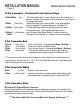
REMOTE VEHICLE STARTER INSTALLATION MANUAL Page 5 Wiring Diagram- 35xx Series (+) 30amp Output Starter Output Heater/Acc Output Power Input Power Input Selectable Output Ignition Output YELLOW GREEN RED RED WHITE BLUE (-)500ma Output Factory Re-arm Output (-)500ma Output Starter Kill/Anti-Grind Output Yellow Orange (+) 30amp Output (+) 30amp Output (+) 30amp Input (+) 30amp Input (+) 30amp Output (-)500ma Output (-)500ma Output (-)500ma Output Factory Dis-arm Output Brown Trunk Release Output
INSTALLATION MANUAL REMOTE VEHICLE STARTER Page 6 Module Side View Not Available Temperature Sensor Input Note: If the Temperature Sensor is installed the Cold Start Mode will operate by monitoring temperate. If the sensor is not installed the Cold Start Mode will function as Timer Mode. The temperature sensor can be installed under the hood strapped to the radiator hose to monitor coolant temperature or left mounted under the dash to monitor ambient air temperature.
REMOTE VEHICLE STARTER INSTALLATION MANUAL Page 7 6 Pin Power Connector 6-pin 1-Yellow 2-Green 3-Red 4-Red 5-Blue 6-White Description 30amp Starter Output Test For Wire This wire will test 0volts in off, accessory and in the ignition position.12volts during start only. 30amp Heat/Acc Output This wire will test 0volts in the off position 1214volts in the accessory and run positions and 0 volts during start 30amp Power Input 12volts at ignition harness or from battery.
INSTALLATION MANUAL REMOTE VEHICLE STARTER Page 8 14 Pin Connector - Continued From Previous Page 11-Blue/White Tach A/C Tach Signal Input. Used to detect when the vehicle has started. This wire is connected to the vehicles coil, fuel injector or crank sensor wire. 12-Blue Glow Plug Diesel Glow plug input, detects both 12volt and negative glow plug signals. Programmable input. See Menu 3 13-White Park Lights +10amp park light output.
REMOTE VEHICLE STARTER INSTALLATION MANUAL Page 9 Step 1 - Connect All Of the Following Wires 6 Pin Power Connector Yellow Green Red Red Blue White 30amp Starter Output 30amp Heater Output 12volts during start position only. 12volts in the accessory position off during start and 12volts during run. 30amp Power Input Constant 12volt power at ignition harness or from the battery. 30amp Power Input Constant 12volt power at ignition harness or from the battery.
INSTALLATION MANUAL REMOTE VEHICLE STARTER Page 10 Manual Transmission “M” Models Never install an automatic transmission remote starter into a manual transmission vehicle!!! Doing so may result in serious injury or death. Do not install remote starters in convertible vehicles! The following wires must be connected In addition to the basic remote starter installation. Park Brake Input- This wire is located at the park brake switch. The wire will switch to (-) when the park brake is applied.
REMOTE VEHICLE STARTER INSTALLATION MANUAL Page 11 Auto Tach Learn 1) Turn the ignition key to the “ON” position. (The park lights will turn on*). 2) Start the vehicle with the key, The LEDs on the antenna will turn on if a proper tach signal is detected**, then after 30-35 seconds the park lights will flash and the horn (Optional) will honk twice to confirm Tach Learn. * If the park lights do not turn on check for proper connection on the BLUE ignition wire at the 6-pin connector.
INSTALLATION MANUAL REMOTE VEHICLE STARTER Page 12 Important Tach Notes Tach Learning the remote starter is one of the most important steps in the installation process. Do not tach learn vehicle while the engine is in high idle. To ensure the best possible tach setting, ensure that the vehicle is at low idle/ normal operating RPM. Vehicles such as Toyota and Honda may idle much higher when the engine is warm compared to starting the vehicle when the engine is cold.
REMOTE VEHICLE STARTER INSTALLATION MANUAL Page 13 Entering Program Mode 1) With the ignition in the OFF position, turn the ignition key from “Off” to “On” 3 times, ON-OFF-ON-OFF-ON within three seconds. (Leave the key in the ON position) 2) Press and release the Program Button located on the antenna. The park lights will flash and the horn (optional) will honk to confirm entering program mode. 3) Select desired Program Menu (See below).
INSTALLATION MANUAL REMOTE VEHICLE STARTER Page 14 Quick View Programming * See the following pages for more detailed programming instructions.
REMOTE VEHICLE STARTER INSTALLATION MANUAL Page 15 Menu 1- User Settings Ignition ON-OFF-ON-OFF-ON Press & Release Program Button Press Lock Button Setting 1 Ignition Auto Lock 1) Ignition Lock & Unlock Enable 1 Flash/Honk Doors Lock/Unlock with Ignition key. 2) Ignition Lock Only 2 Flashes/Honks Doors Lock when ignition is turned ON only. *3) Ignition Auto Lock Disable 3 Flashes/Honks Doors do not Lock/Unlock with Ignition key.
INSTALLATION MANUAL REMOTE VEHICLE STARTER Page 16 Menu 2- Additional Settings Ignition ON-OFF-ON-OFF-ON Press & Release Program Button Press Unlock Setting 1 Secure Valet Mode - Length of time required to set the system into Service Mode 1) Secure Valet 1 Flash/Honk Hold the Program Button for 15 seconds *2) Normal Valet 2 Flashes/Honks Hold the Program Button for 5 seconds Press & Release the Program Button 1 Time (Setting 1) confirmed 1 LED flashes.
REMOTE VEHICLE STARTER INSTALLATION MANUAL Page 17 Menu 3- Starter Settings Ignition ON-OFF-ON-OFF-ON Press & Release Program Button Press Start Button Setting 1 Special Door Lock/Unlock Operations (Factory Alarm Rearm). 1) Type 1 1 Flash/Honk Unlock pulse before start. Lock pulse after start and on shutdown. 2) Type 2 2 Flashes/Honks Lock pulse ONLY after remote start shutdown. *3) Type 3 3 Flashes/Honks Default Lock/ Unlock Pulses.
INSTALLATION MANUAL REMOTE VEHICLE STARTER Page 18 Menu 3- Starter Settings - Continued From Previous Page Setting 5 Maximum Crank Time 1) 10 Seconds 1 Flash/Honk 10 sec max time that the starter will stay engaged. 2) 3 Seconds 2 Flashes/Honks 3 sec max time that the starter will stay engaged. *3) 5 Seconds 3 Flashes/Honks 5 sec max time that the starter will stay engaged. Press & Release the Program Button 5 Times (Setting 5) Confirmed with 5 LED flashes.
REMOTE VEHICLE STARTER INSTALLATION MANUAL Page 19 Menu 4- Tach Settings Setting 1 Auto Tach Learn. 1) 2) 3) 4) Perform a System Reset. See page 15. Turn the ignition key on. (Park lights will turn on). Start the vehicle, the LEDs on the antenna will come on when a proper tach signal is detected*. After approximately 30-35 seconds the park lights will go out then will flash twice and the horn (optional) will honk twice to confirm that a tach signal has been learned.
INSTALLATION MANUAL REMOTE VEHICLE STARTER Page 20 Service Mode ATTENTION: TO AVOID SERIOUS INJURY, this remote start system must be set into Service Mode before any under hood servicing is started. Service Mode will prevent the vehicle from starting while the vehicle is being serviced. It is the sole responsibility of the vehicle’s owner to place the system into Service Mode. The manufacture accepts no responsibility for accidental starting of the vehicle while the vehicle is being serviced.
INSTALLATION MANUAL REMOTE VEHICLE STARTER Page 21 Transmitter Programming Step 1 - Within 3 seconds turn the ignition ON-OFF-ON-OFF-ON - Leaving Key ON Step 2 - Press and hold the Program Button - The park lights will turn ON and the siren will chirp once.* Continue to hold the Program Button, the park lights will turn off and the siren will chirp 5 times quickly. Step 3 - While holding the Program Button, press the LOCK button on each of the remote’s to be programmed.
INSTALLATION MANUAL REMOTE VEHICLE STARTER Page 22 Negative Type Door Locks 250ma Vehicle Lock/Unlock Switch Lock To Control Relay or Actuators Un lock Green Blue Negative Door Locks (More Than 250ma) Fused +12V Vehicle Lock/Unlock Switch Ground Green 87 87 87a 86 87a 85 Blue Un Lock lock 86 85 30 30 To Control Relay or Actuator Positive Type Door Locks Un Lock lock Fused +12V Green 87 87 87a 86 Blue Vehicle Lock/Unlock Switch 87a 85 30 86 85 30 To Control Relay or Actuator
INSTALLATION MANUAL REMOTE VEHICLE STARTER Page 23 5 Wire / Reverse Polarity Type Door Locks Fused +12V 87 Green 87 87a 86 Blue 85 30 Lock Vehicle Lock/Unlock Switch 87a 86 85 30 x Cut Un lock To Actuator x Cut Aftermarket Doorlock Actuators Ground 87 87a 86 85 30 Vacuum Type Door Locks DIAGNOSTICS Ground Fused +12V Blue Lock Un lock 87 87 87a 87a 86 85 86 30 85 30 x Cut Note: When installing relays always use a fused power source.
INSTALLATION MANUAL REMOTE VEHICLE STARTER Page 24 DIAGNOSTICS If the remote starter does not activate when the start button is pressed the park lights will flash a diagnostic to indicate what shutdown input has been triggered. For example when the start button is pressed the park lights flash 3 times slowly.